A hybrid T-type multilevel inverter device and its control method
A technology of multi-level inverter and control method, which is applied in the direction of output power conversion device, electrical components, AC power input conversion to DC power output, etc. It can solve the problems of limiting the application range and the increase of the maximum voltage stress, and achieves the expansion Application range, low voltage stress, and the effect of solving large voltage stress
- Summary
- Abstract
- Description
- Claims
- Application Information
AI Technical Summary
Problems solved by technology
Method used
Image
Examples
Embodiment 1
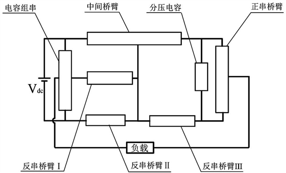
[0048] A hybrid T-type multilevel inverter device, which is set at a DC voltage source V dc and load, as attached figure 1 As shown, it includes capacitor strings, reverse series bridge arm I, reverse series bridge arm II, reverse series bridge arm III, intermediate bridge arm, voltage dividing capacitor and positive series bridge arm; the capacitor string and the DC voltage source V dc connected in parallel; the central point of the capacitor string is connected to one end of the reverse series bridge arm I, and the other end of the reverse series bridge arm I is respectively connected to the first connection end of the intermediate bridge arm and the reverse series bridge arm II One end of the reverse series bridge arm III is connected to one end to form a T-shaped bridge arm; the reverse series bridge arm I, the reverse series bridge arm II, the reverse series bridge arm III, the intermediate bridge arm and the partial pressure The capacitor forms a switched capacitor unit...
Embodiment 2
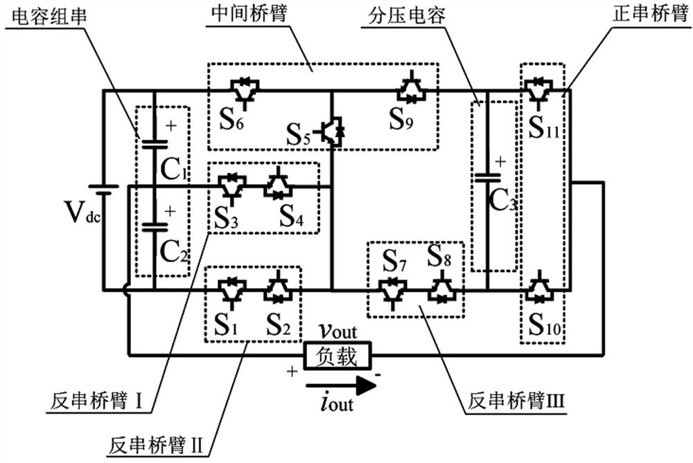
[0055] as attached figure 2 As shown, this embodiment describes the topology structure of the hybrid T-type multilevel inverter device in detail.
[0056] This embodiment provides a specific implementation of a capacitor string, which includes an equivalent capacitor C connected in series in the forward direction. 1 and equivalent capacitance C 2 , the equivalent capacitance C 1 The anode of the DC voltage source V is connected dc positive pole, the equivalent capacitance C 2 The cathode is connected to the DC voltage source V dc of the negative pole, the equivalent capacitance C 1 of the cathode and the equivalent capacitance C 2 The anodes are connected to one end of the load respectively.
[0057] This embodiment also provides a specific implementation of a positive series bridge arm, the positive series bridge arm is used as a direction changing unit, including a switch tube S connected in series in the forward direction 10 and switch tube S 11 , the switching tu...
Embodiment 3
[0081] In this embodiment, the hybrid T-type multilevel inverter device and its control method are verified through simulation. Setup: DC input voltage is 30V, load is 50Ω-100mH, capacitance is 2200μF, switching frequency is 2kHz.
[0082] According to the above control method, the hybrid T-type multilevel inverter device is modulated, as shown in the attached Figure 11 As shown, this embodiment gives the output voltage v of the hybrid T-type multilevel inverter device out and output current i out The simulation waveform of the output voltage and output current is stable, and meets the working conditions of the inverter; the hybrid T-type multi-level inverter device can output the correct target waveform, and the load current is a smooth sinusoidal waveform. The correctness of the hybrid T-type multilevel inverter device and its control method is verified.
[0083] as attached Figure 12 As shown, this embodiment provides the simulation waveform of the capacitor ripple of...
PUM
 Abstract
Description
Claims
Application Information
 - R&D
- Intellectual Property
- Life Sciences
- Materials
- Tech Scout
- Unparalleled Data Quality
- Higher Quality Content
- 60% Fewer Hallucinations
Browse by: Latest US Patents, China's latest patents, Technical Efficacy Thesaurus, Application Domain, Technology Topic, Popular Technical Reports.
© 2025 PatSnap. All rights reserved.Legal|Privacy policy|Modern Slavery Act Transparency Statement|Sitemap|About US| Contact US: help@patsnap.com


