Hybrid T-type multi-level inversion device and control method thereof

A technology of multi-level inverter and control method, which is applied in the direction of output power conversion device, electrical components, AC power input conversion to DC power output, etc. It can solve the problems of maximum voltage stress increase and limit application range, etc., to achieve Low voltage stress, extended application range, and the effect of solving large voltage stress

Active Publication Date: 2019-12-13
ZHENGZHOU UNIV
View PDF6 Cites 5 Cited by
  • Summary
  • Abstract
  • Description
  • Claims
  • Application Information

AI Technical Summary

Problems solved by technology

[0005] At present, there are switched capacitor multilevel inverters in the prior art, but the maximum voltage stress on the switching device increases with the increase of the output voltage gain, which limits its application range to a certain extent

Method used


Image

  • Hybrid T-type multi-level inversion device and control method thereof
  • Hybrid T-type multi-level inversion device and control method thereof
  • Hybrid T-type multi-level inversion device and control method thereof

Examples


Embodiment 1

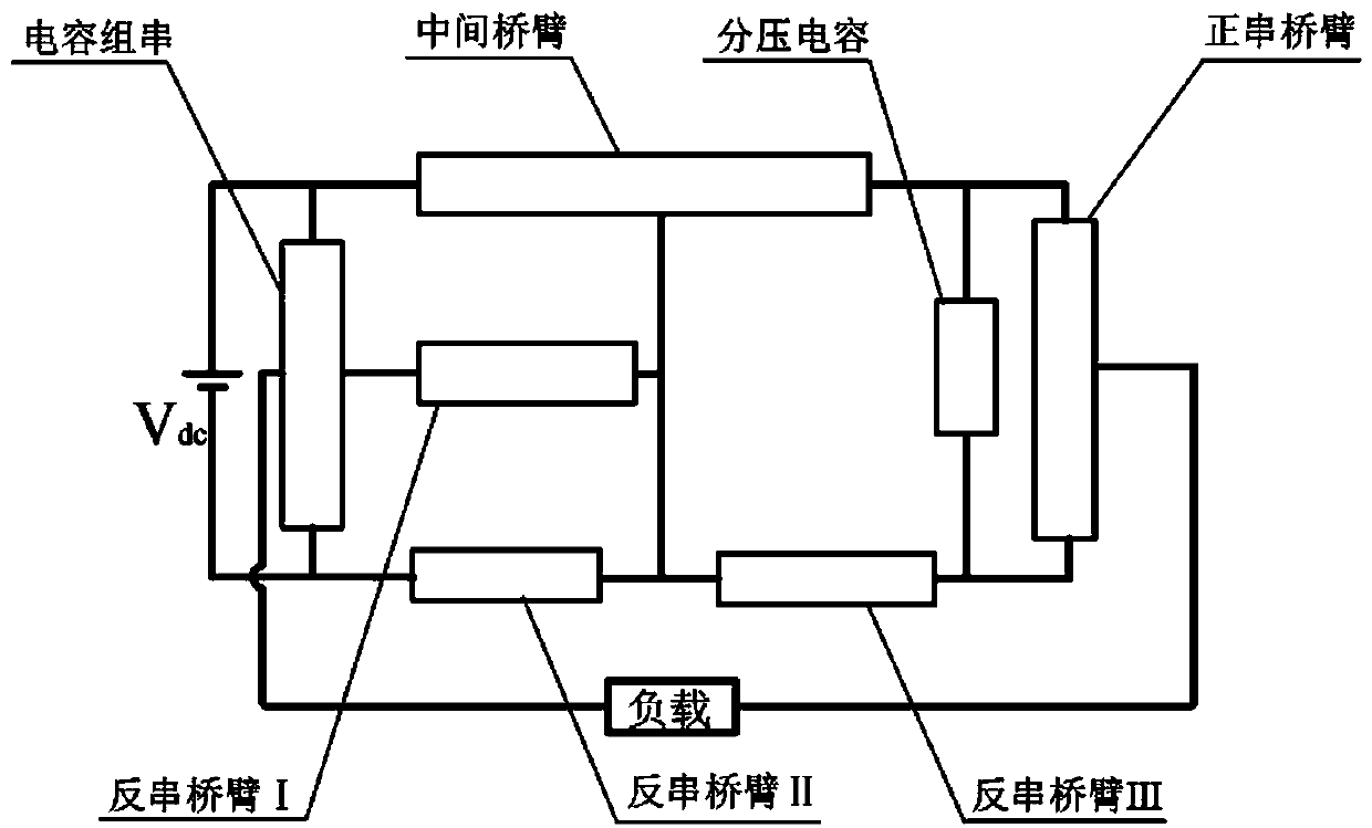
[0048] A hybrid T-type multilevel inverter device, which is set at a DC voltage source V dc and load, as attached figure 1 As shown, it includes capacitor strings, reverse series bridge arm I, reverse series bridge arm II, reverse series bridge arm III, intermediate bridge arm, voltage dividing capacitor and positive series bridge arm; the capacitor string and the DC voltage source V dc connected in parallel; the central point of the capacitor string is connected to one end of the reverse series bridge arm I, and the other end of the reverse series bridge arm I is respectively connected to the first connection end of the intermediate bridge arm and the reverse series bridge arm II One end of the reverse series bridge arm III is connected to one end to form a T-shaped bridge arm; the reverse series bridge arm I, the reverse series bridge arm II, the reverse series bridge arm III, the intermediate bridge arm and the partial pressure The capacitor forms a switched capacitor unit...

Embodiment 2

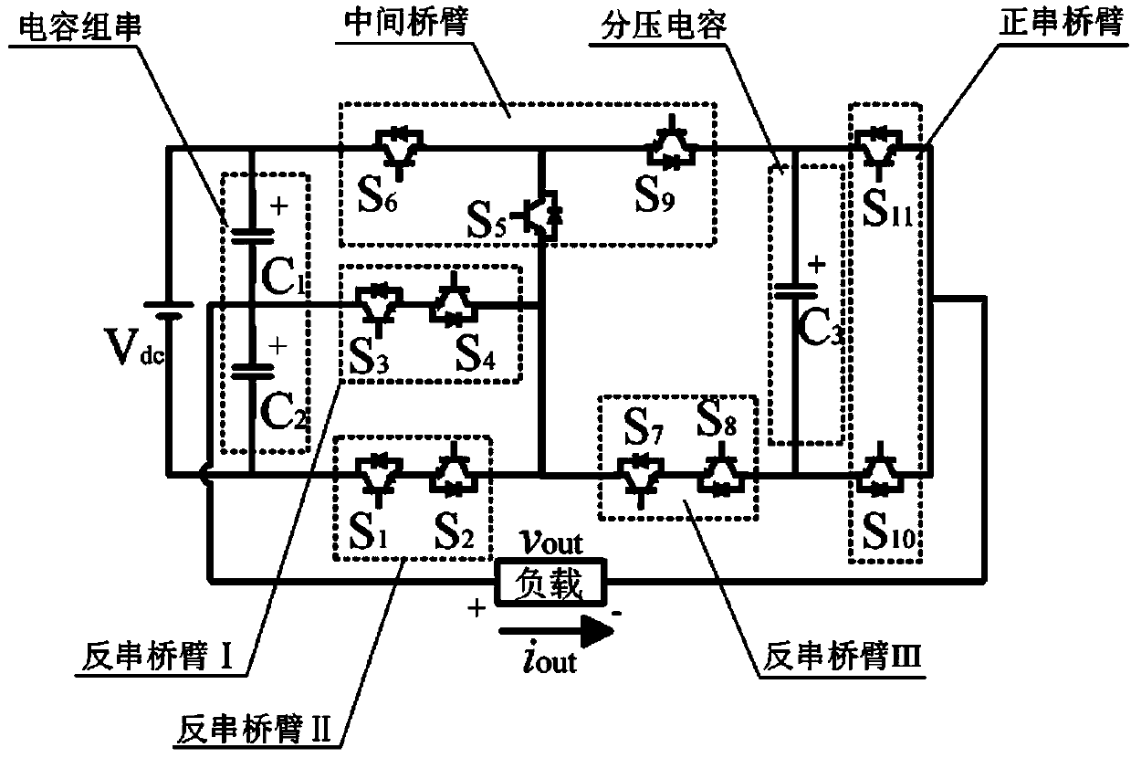
[0054] as attached figure 2 As shown, this embodiment describes the topology structure of the hybrid T-type multilevel inverter device in detail.

[0055] This embodiment provides a specific implementation of a capacitor string, which includes an equivalent capacitor C connected in series in the forward direction. 1 and equivalent capacitance C 2 , the equivalent capacitance C 1 The anode of the DC voltage source V is connected dc positive pole, the equivalent capacitance C 2 The cathode is connected to the DC voltage source V dc of the negative pole, the equivalent capacitance C 1 of the cathode and the equivalent capacitance C 2 The anodes are connected to one end of the load respectively.

[0056] This embodiment also provides a specific implementation of a positive series bridge arm, the positive series bridge arm is used as a direction changing unit, including a switch tube S connected in series in the forward direction 10 and switch tube S 11 , the switching tu...

Embodiment 3

[0080] In this embodiment, the hybrid T-type multilevel inverter device and its control method are verified through simulation. Setup: DC input voltage is 30V, load is 50Ω-100mH, capacitance is 2200μF, switching frequency is 2kHz.

[0081] According to the above control method, the hybrid T-type multilevel inverter device is modulated, as shown in the attached Figure 11 As shown, this embodiment gives the output voltage v of the hybrid T-type multilevel inverter device out and output current i out The simulation waveform of the output voltage and output current is stable, and meets the working conditions of the inverter; the hybrid T-type multi-level inverter device can output the correct target waveform, and the load current is a smooth sinusoidal waveform. The correctness of the hybrid T-type multilevel inverter device and its control method is verified.

[0082] as attached Figure 12 As shown, this embodiment provides the simulation waveform of the capacitor ripple of...


PUM


Abstract

The invention provides a hybrid T-type multi-level inversion device and a control method thereof. In the inversion device, a capacitor bank string is connected with a DC voltage source Vdc in parallel; the central point of the capacitor bank string is connected with one end of a first reverse-series bridge arm, the other end of the first reverse-series bridge arm is respectively connected with a first connecting end of a middle bridge arm, one end of a second reverse-series bridge arm and one end of a third reverse-series bridge arm, and a T-shaped bridge arm is formed; the first reverse-series bridge arm, the second reverse-series bridge arm, the third reverse-series bridge arm, the middle bridge arm and a voltage-dividing capacitor form a switched capacitor unit; a positive series bridgearm is connected in parallel with the voltage-dividing capacitor; and the central point of the positive series bridge arm and the central point of the capacitor bank string serve as AC voltage outputends of the hybrid T-shaped multi-level inversion device. The technical problem of overlarge voltage stress borne by the switching tube due to increase of output voltage in the switched capacitor multi-level inverter is effectively solved, so that the multi-level inverter is suitable for high-voltage and high-power occasions, and the application range of the inverter is expanded.

Description

technical field [0001] The invention relates to the fields of electric energy conversion and new energy power generation, distributed grid-connected power generation and high-voltage large working conditions, and specifically relates to a hybrid T-type multi-level inverter device and a control method thereof. Background technique [0002] With the increasingly serious environmental pollution, the application of clean and renewable energy has attracted much attention, and research in the fields of photovoltaic power generation, wind power generation, and electric vehicles has gradually increased, and inverters, as the core of them, have also become the focus of research. Multi-level inverter technology overcomes the disadvantages of high output harmonic content and large voltage stress of traditional inverters, and is widely used in production and life. Traditional multilevel inverters mainly include diode clamp type, flying capacitor type and cascaded type. Among them, diod...

Claims


Application Information

Patent Timeline
Patent Type & Authority Applications(China)
IPC IPC(8): H02M7/483
CPCH02M7/483
Inventor 王要强库若含梁军王明东董亮辉陈根永袁艺森王昌龙
Owner ZHENGZHOU UNIV
Why Eureka
Try Eureka