Non-bridge type multilevel converter and control method thereof

A conversion device and multi-level technology, applied in the direction of output power conversion device, high-efficiency power electronic conversion, conversion of AC power input to DC power output, etc., can solve the problems of increasing and limiting converters

Active Publication Date: 2020-10-02
ZHENGZHOU UNIV
View PDF4 Cites 2 Cited by
  • Summary
  • Abstract
  • Description
  • Claims
  • Application Information

AI Technical Summary

Problems solved by technology

[0005] The current method is to introduce switched capacitor technology into the conversion topology. Through the combination of switching devices and capacitors, multi-level output can be realized, which has the advantages of high efficiency, large voltage gain, and small size....

Method used


Image

  • Non-bridge type multilevel converter and control method thereof
  • Non-bridge type multilevel converter and control method thereof
  • Non-bridge type multilevel converter and control method thereof

Examples


Embodiment 1

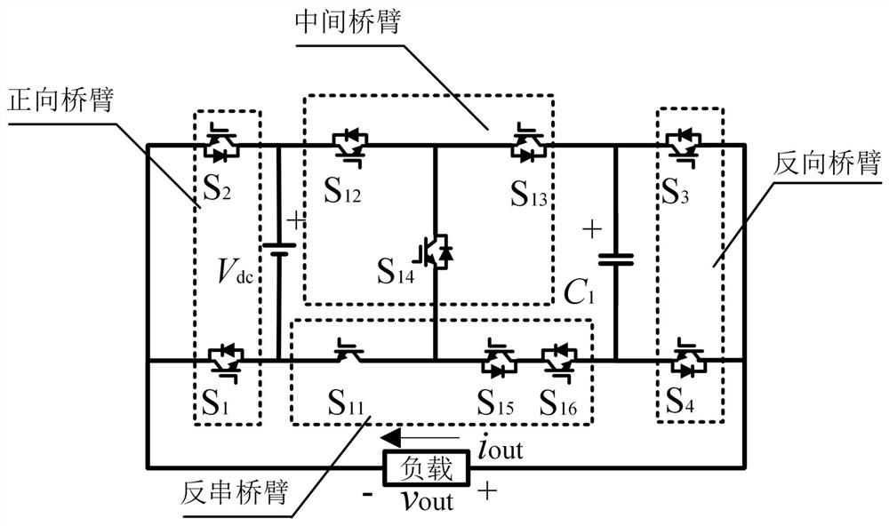
[0040] Such as figure 1 As shown, a non-bridge multilevel conversion device is set at the DC voltage source V dc Between the load and the forward bridge arm, the reverse bridge arm, the intermediate bridge arm, the reverse series bridge arm, and the capacitor C 1 and reverse bridge arm;

[0041]The forward bridge arm includes a switch tube S connected in series 1 and switch tube S 2 , the switching tube S 1 collector and the switch S 2 The emitter is connected and the midpoint position is used to connect one end of the load, the switching tube S 1 The emitter is connected to a DC voltage source V dc the negative pole of the switching tube S 2 The collector is connected to the DC voltage source V dc positive pole.

[0042] The intermediate bridge arm includes a switch tube S 12 , switch tube S 13 and switch tube S 14 , the switching tube S 12 The collector is connected to the DC voltage source V dc positive pole of the switching tube S 13 The emitter of the switc...

Embodiment 2

[0074] Such as Figure 12 shown, the DC voltage source V dc At least two switched capacitor units are arranged between the reverse bridge arm and the reverse bridge arm, and the output voltage gain increases by V for each additional switched capacitor unit. dc , the number of output levels is 2n+1. In addition, since the extended structure is composed of n switched capacitor units, the maximum voltage stress borne by each switch tube is still V dc , the present invention effectively solves the technical problem of excessive voltage stress on the switch tube due to the increase of the output voltage in the switched capacitor multilevel converter, making the present invention suitable for medium and high voltage occasions and expanding the application range of the converter.

Embodiment 3

[0076] A non-bridge multilevel conversion system, comprising a controller and a multilevel conversion device, the multilevel conversion device is the non-bridge multilevel conversion device, and the controller controls the non-bridge When the switching tube in the non-bridge type multilevel conversion device operates, the control method of the non-bridge type multilevel conversion device is executed. The controller includes DSP, FPGA and peripheral circuits, and the controller communicates with the multi-level conversion device to realize the adjustment of the working mode by adjusting the on-off of the switch tube.


PUM


Abstract

The invention provides a non-bridge type multi-level conversion device which is arranged between a direct-current voltage source Vdc and a load and comprises a forward bridge arm, a reverse bridge arm, a middle bridge arm, a reverse series bridge arm, a capacitor C1 and a reverse bridge arm. The middle bridge arm, the reverse series bridge arm and the capacitor C1 form a switched capacitor unit, the number of the switched capacitor units can be expanded, and the multi-level output is achieved through the switching under different working modes. Meanwhile, the voltage stress borne by a switching tube is not too large along with the increase of the output voltage, and the maximum voltage stress borne by the switching tube does not exceed the input voltage at the direct-current side, so thatthe application problem under the medium-high voltage occasions is solved.

Description

technical field [0001] The invention relates to the fields of power electronics and electric energy conversion, new energy power generation and distribution, and more specifically relates to a non-bridge multilevel conversion device and a control method thereof. Background technique [0002] Multilevel converters are composed of components such as DC power supplies, active switches, and power diodes. They can generate voltage waveforms with low total harmonic distortion and play an important role in energy conversion systems such as photovoltaic power generation. [0003] Traditional multilevel converters are generally divided into diode clamp type, flying capacitor type and cascaded H-bridge type. Among them, the diode clamp type and the flying capacitor type multilevel converter use a large number of clamp diodes and clamp capacitors to increase the number of output levels, but their circuit structure is complex, which increases the difficulty of control. The cascaded mul...

Claims


Application Information

Patent Timeline
IPC IPC(8): H02M7/483H02M7/5387
CPCH02M7/483H02M7/53871H02M1/007H02M7/4835Y02E10/56
Inventor 王要强库若含刘陈王克文陈根永梁军
Owner ZHENGZHOU UNIV
Why Eureka
Try Eureka