Power control method, user equipment, base station and communication system of dimension to dimension (D2D)

A technology of power control and user equipment, applied in the field of communication, can solve the problems such as no power adjustment of the UE at the transmitting end, unable to effectively control the transmission power of the UE at the transmitting end, etc., and achieve the effect of power control

Active Publication Date: 2013-06-05
HONOR DEVICE CO LTD
View PDF9 Cites 93 Cited by
  • Summary
  • Abstract
  • Description
  • Claims
  • Application Information

AI Technical Summary

Problems solved by technology

However, in the current D2D method, there is no method for adjusting the power of the UE at the send

Method used


Image

  • Power control method, user equipment, base station and communication system of dimension to dimension (D2D)
  • Power control method, user equipment, base station and communication system of dimension to dimension (D2D)
  • Power control method, user equipment, base station and communication system of dimension to dimension (D2D)

Examples


Embodiment 1

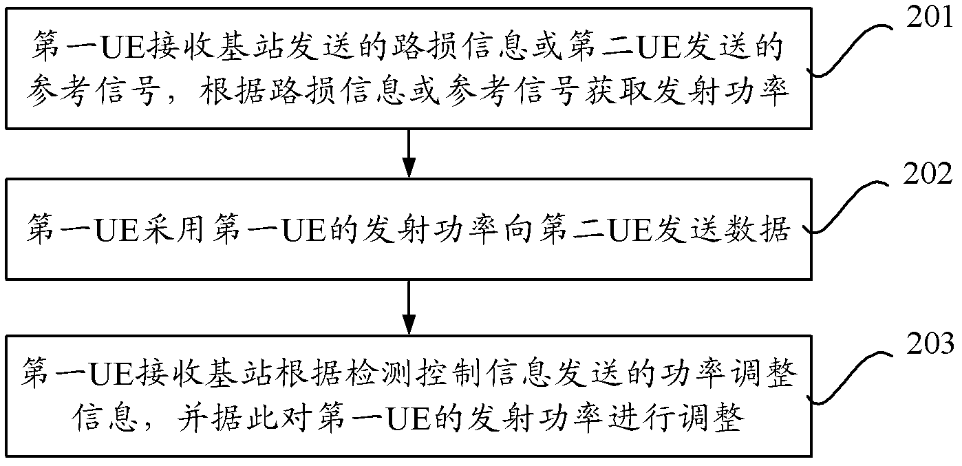
[0049] An embodiment of the D2D power control method of the present invention is as follows figure 2 shown, including:

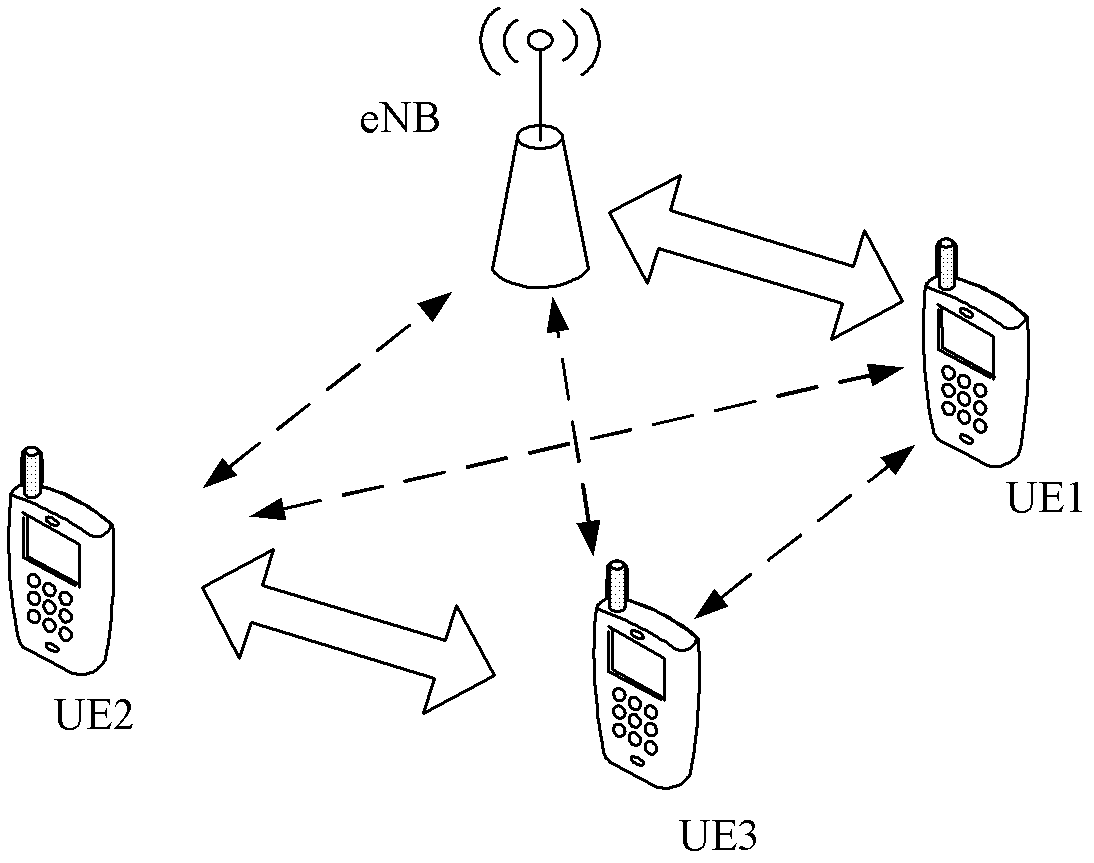
[0050]201. The first UE receives path loss information sent by a base station or a reference signal sent by a second UE, and acquires transmit power of the first UE according to the path loss information or the reference signal.

[0051] Optionally, when the first UE receives the reference signal sent by the second UE, the reference signal may be a sounding reference signal (Sounding Reference Signal, SRS for short) or a demodulation reference signal (Demodulation Reference Signal, DM-RS for short). . In this embodiment, for example, the base station may issue configuration parameters corresponding to the reference signal to the first UE and the second UE respectively in advance, for example, issue configuration parameters for instructing to send the SRS (for example, SRS bandwidth, frequency domain location, etc.), the second UE can send the SRS accordin...

Embodiment 2

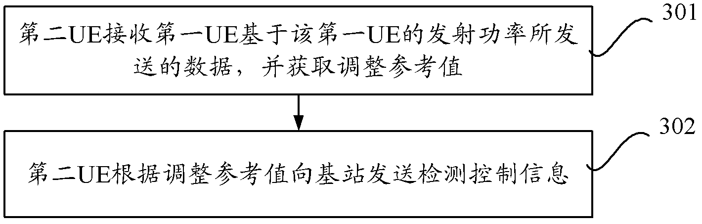
[0064] Another embodiment of the D2D power control method of the present invention is as follows image 3 shown, including:

[0065] 301. The second UE receives data sent by the first UE based on the transmit power of the first UE, and acquires an adjustment reference value.

[0066] Optionally, the transmit power used by the first UE is obtained by the first UE according to path loss information sent by the base station or a reference signal sent by the second UE.

[0067] Optionally, when the first UE acquires transmit power according to the reference signal sent by the second UE, the second UE will receive in advance the configuration parameter sent by the base station for instructing to send the reference signal, and send the configuration parameter according to the configuration parameter. the reference signal. The reference signal is, for example, SRS or DM-RS.

[0068] After receiving the reference signal, the first UE can obtain the received power of the reference s...

Embodiment 3

[0076] Another embodiment of the D2D power control method of the present invention is as follows: Figure 4 shown, including:

[0077] 401. The base station sends path loss information to a first user equipment UE, or sends reference signal indication information to a first UE and a second UE.

[0078] Wherein, the indication information is used to instruct the first UE to receive the reference signal sent by the second UE, or to instruct the second UE to send the reference signal to the first UE.

[0079] 402. The base station receives detection control information sent by the second UE according to the adjusted reference value.

[0080] Wherein, the adjustment reference value is obtained by the second UE according to the data sent by the first UE using transmission power, and the transmission power is obtained by the first UE according to path loss information sent by the base station or a reference signal sent by the second UE.

[0081] Optionally, for example, the refere...


PUM


Abstract

The invention provides a power control method, user equipment, a base station and a communication system of dimension to dimension (D2D). The power control method comprises that a first user equipment (UE) receives path loss information sent by the base station or reference signals sent by a second UE, transmission power of the first UE is obtained through the path loss information or the reference signals, data is sent to the second EU based on the transmission power of the first UE so that the second EU obtains adjustment reference value according to the data and sends detection control information to the base station according to the adjustment reference value, and the first UE receives the power adjustment information sent by the base according to the detection control information and adjusts the transmission power of the first UE according to the power adjustment information. The power control method, the user equipment, the base station and the communication system of the D2D achieve power control of a transmitting end device in the D2D.

Description

technical field [0001] The present invention relates to communication technology, in particular to a D2D power control method, user equipment, base station and communication system. Background technique [0002] In a wireless communication system, in order to overcome the influence of path loss and make the signal reach a specified signal quality, it is usually necessary to adjust and control the transmission power of a user equipment (user equipment, UE for short) at the sending end. Generally, the method adopted is that UE at the sending end sends a power headroom report (Pewer Headroom Report, PHR for short) to the base station periodically, and reports the difference between the transmit power and the maximum transmit power of the UE, that is, the power headroom report (Pewer Headroom Report, PHR for short). : PH), so that the base station can adjust the transmit power of the UE according to the PH. Among them, when the UE calculates the transmission power, it needs to ...

Claims


Application Information

Patent Timeline
IPC IPC(8): H04W52/18H04W52/24
CPCH04W52/383H04W52/386H04W52/242H04W52/18
Inventor 戴明增曾清海
Owner HONOR DEVICE CO LTD
Why Eureka
Try Eureka