Supercharge Your Innovation With Domain-Expert AI Agents!

Heat dissipation module and its configuration method

A technology of heat dissipation module and structure, which is applied in the direction of cooling/ventilation/heating transformation, etc. It can solve the problems of high thermal resistance of heat pipes and heat dissipation fins, and the inability to effectively use heat dissipation fins to dissipate heat, so as to reduce heat resistance and improve heat dissipation efficiency Effect

Active Publication Date: 2017-06-30
GIGA BYTE TECH CO LTD
View PDF4 Cites 0 Cited by
  • Summary
  • Abstract
  • Description
  • Claims
  • Application Information

AI Technical Summary

Problems solved by technology

[0008] However, the junction form of the heat pipe and the cooling fins in the prior art only forms a groove at the edge of each cooling fin, and the heat supply pipe is placed, so the heat pipe is not in close contact with each cooling fin, causing the heat pipe and the cooling fin to The thermal resistance between them is too high, so that the fins cannot be effectively used to help the heat pipe dissipate heat

Method used


Image

  • Heat dissipation module and its configuration method
  • Heat dissipation module and its configuration method
  • Heat dissipation module and its configuration method

Examples


Embodiment Construction

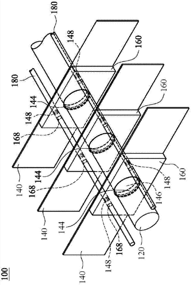
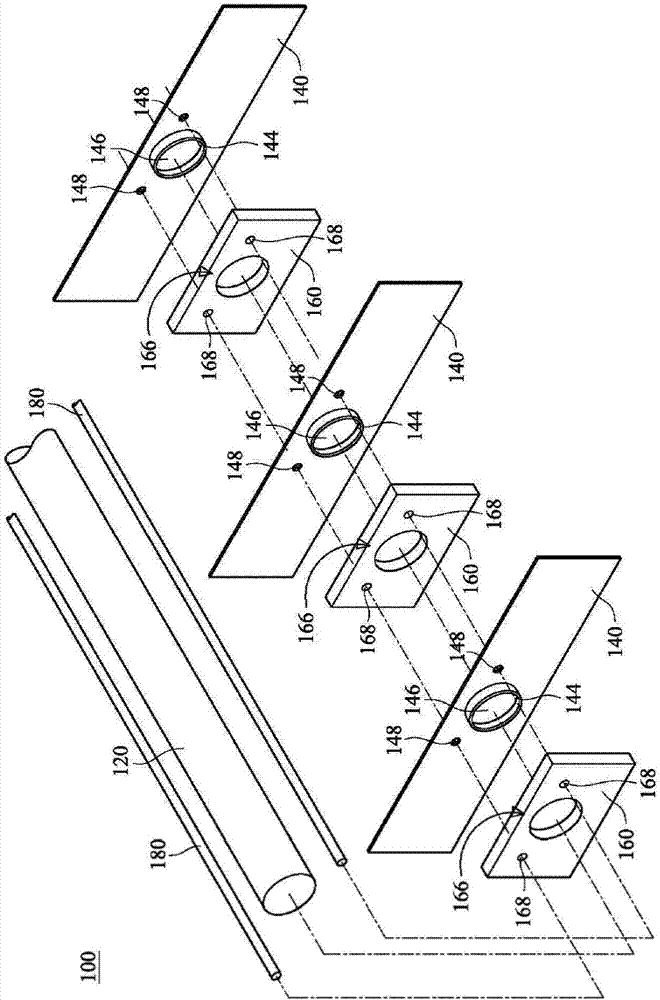
[0052] see figure 1 and figure 2, are respectively a three-dimensional assembled view and a three-dimensional exploded view of the heat dissipation module 100 according to an embodiment of the present invention. The function of the heat dissipation module 100 disclosed in this embodiment of the present invention is to press the extension part 144 of the heat dissipation fin 140 by pressing the clip 160, so that the extension part 144 is partially recessed into the outer surface of the heat pipe 120 to face The heat pipe 120 forms a clamping force, thereby enhancing the heat dissipation performance of the heat dissipation module 100 of the present invention.

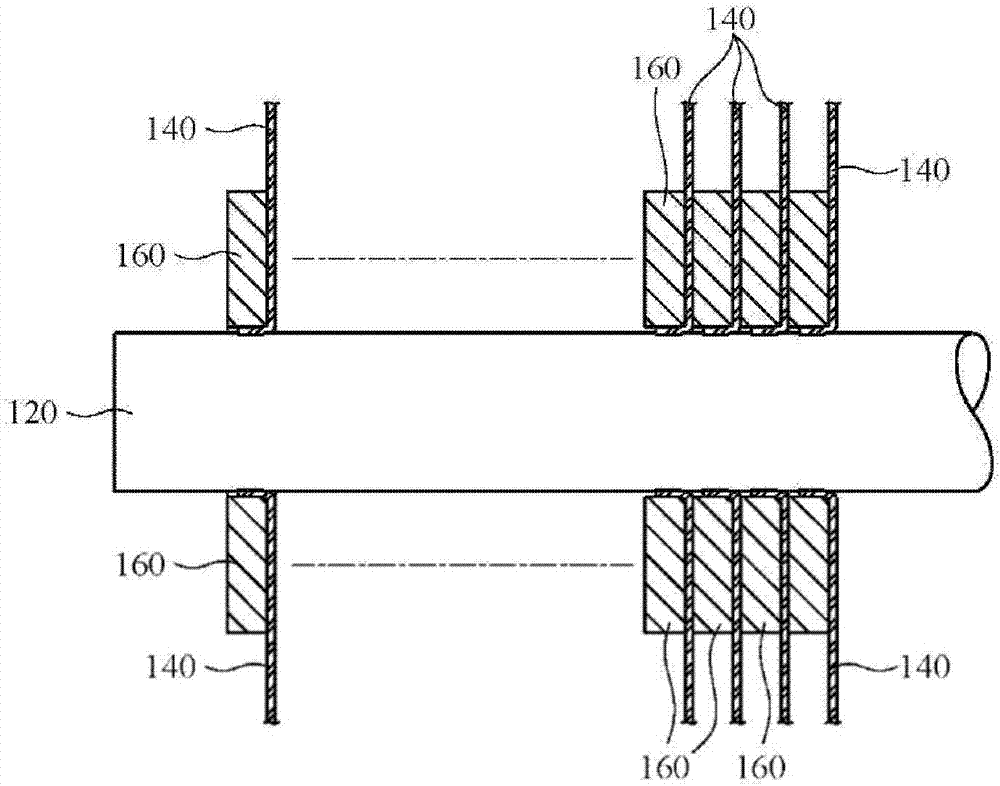
[0053] image 3 Shown is a schematic plan view of a heat dissipation module 100 according to an embodiment of the present invention, Figure 4 for image 3 A partial enlargement of the . In detail, the heat dissipation module 100 according to an embodiment of the present invention includes a heat pipe 120 , a plural...


PUM


Abstract

The invention relates to a heat dissipation module and its construction method. The heat dissipation module includes a heat pipe, a plurality of heat dissipation fins, and a plurality of pressing clamps, wherein the heat pipe passes through the opening of each heat dissipation fin and the pressing clamps The through holes of the fins, and the heat dissipation fins and the pressing clips are alternately arranged on the outer tube surface of the heat conduction tube, and each heat dissipation fin has an extension part, which is attached to the outer tube surface of the heat conduction tube. Each pressing clip presses against the extension of an adjacent heat dissipation fin, so that the extension is recessed into the outer surface of the heat pipe, thereby enhancing the heat dissipation performance of the heat dissipation module.

Description

[0001] 【Technical field】 [0002] The present invention relates to a heat dissipation module, in particular to a heat dissipation module composed of heat dissipation fins and heat pipes. [0003] 【Background technique】 [0004] With the continuous development of audio-visual, wireless communication and other technologies, electronic components installed on various interface cards, such as central processing unit (central processing unit, CPU), video graphics array (video graphics array, VGA) chips, graphics chips, etc. The microprocessor and its surrounding memory generate a lot of heat during operation. If the heat cannot be effectively dissipated, the interface card will become unstable when it is running at high speed. Therefore, in the conventional technology, a heat dissipation device is installed on the interface card at a position corresponding to the electronic components to dissipate heat. [0005] The traditional heat dissipation method is to coat a layer of heat-co...

Claims


Application Information

Patent Timeline
Patent Type & Authority Patents(China)
IPC IPC(8): H05K7/20
Inventor 黄顺治毛黛娟
Owner GIGA BYTE TECH CO LTD
Features
  • R&D
  • Intellectual Property
  • Life Sciences
  • Materials
  • Tech Scout
  • Unparalleled Data Quality
  • Higher Quality Content
  • 60% Fewer Hallucinations
Learn More