Light emitting diode for mounting to a heat sink

a technology of light-emitting diodes and heat sinks, which is applied in the direction of semiconductor devices for light sources, lighting and heating apparatus, and light-emitting support devices. it can solve the problems of reducing the thermal resistance between led devices and conventional light sources, and limiting the application of led lighting components. it can reduce the thermal resistance between led devices and the effect of reducing the thermal resistan

Active Publication Date: 2009-12-01
LUMILEDS
View PDF6 Cites 74 Cited by
  • Summary
  • Abstract
  • Description
  • Claims
  • Application Information

AI Technical Summary

Benefits of technology

[0018]The apparatus may include a thermally conductive material disposed on the second area, the thermally conductive material being operable to form an interface between the second area and the heat sink when the LED apparatus may be mounted on the heat sink thereby lowering a thermal resistance therebetween.
[0029]The apparatus may include a thermally conductive material disposed on the second area, the thermally conductive material being operable to form an interface between the second area and the heat sink when the LED apparatus may be mounted on the heat sink thereby lowering a thermal resistance therebetween.
[0033]The apparatus may include a thermally conductive material disposed on the lower surface of the sub-mount, the thermally conductive material being operable to form an interface between the lower surface and the heat sink when the LED apparatus may be mounted on the heat sink thereby lowering a thermal resistance therebetween.

Problems solved by technology

Soldering may not be a suitable mounting and / or connection solution for lighting industries, which have traditionally relied on relatively low-tech connection and mounting technologies.
Introducing solder technologies into such industries may represent a barrier to wider adoption of LED lighting components.
LEDs are also substantially more compact than traditional lighting devices such as incandescent and florescent bulbs, which presents a problem for heat removal, in that an LED has less surface area available for convective heat transfer to the surrounding air than traditional light bulbs.
Mounting techniques used for conventional light sources (for example, incandescent bulbs, fluorescent tubes, etc) are generally not appropriate for use with LED devices, as conventional light sources generally do not have the same thermal transfer requirements as an LED.
The majority of mounting techniques for conventional light sources are not useful for mounting compact LED sources (for example a powerful LED may be 1 mm×1 mm or smaller).

Method used


Image

  • Light emitting diode for mounting to a heat sink
  • Light emitting diode for mounting to a heat sink
  • Light emitting diode for mounting to a heat sink

Examples


Embodiment Construction

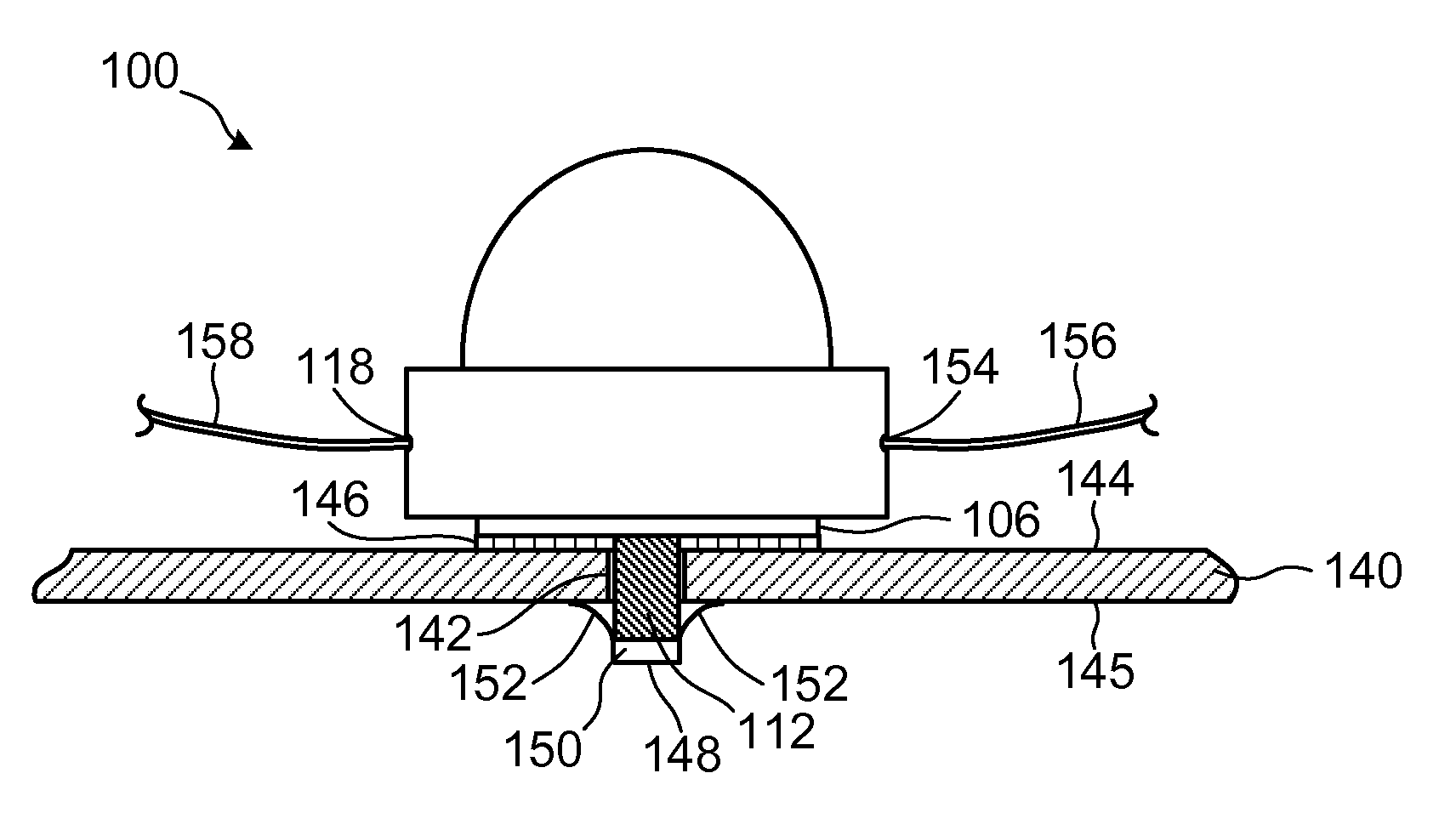
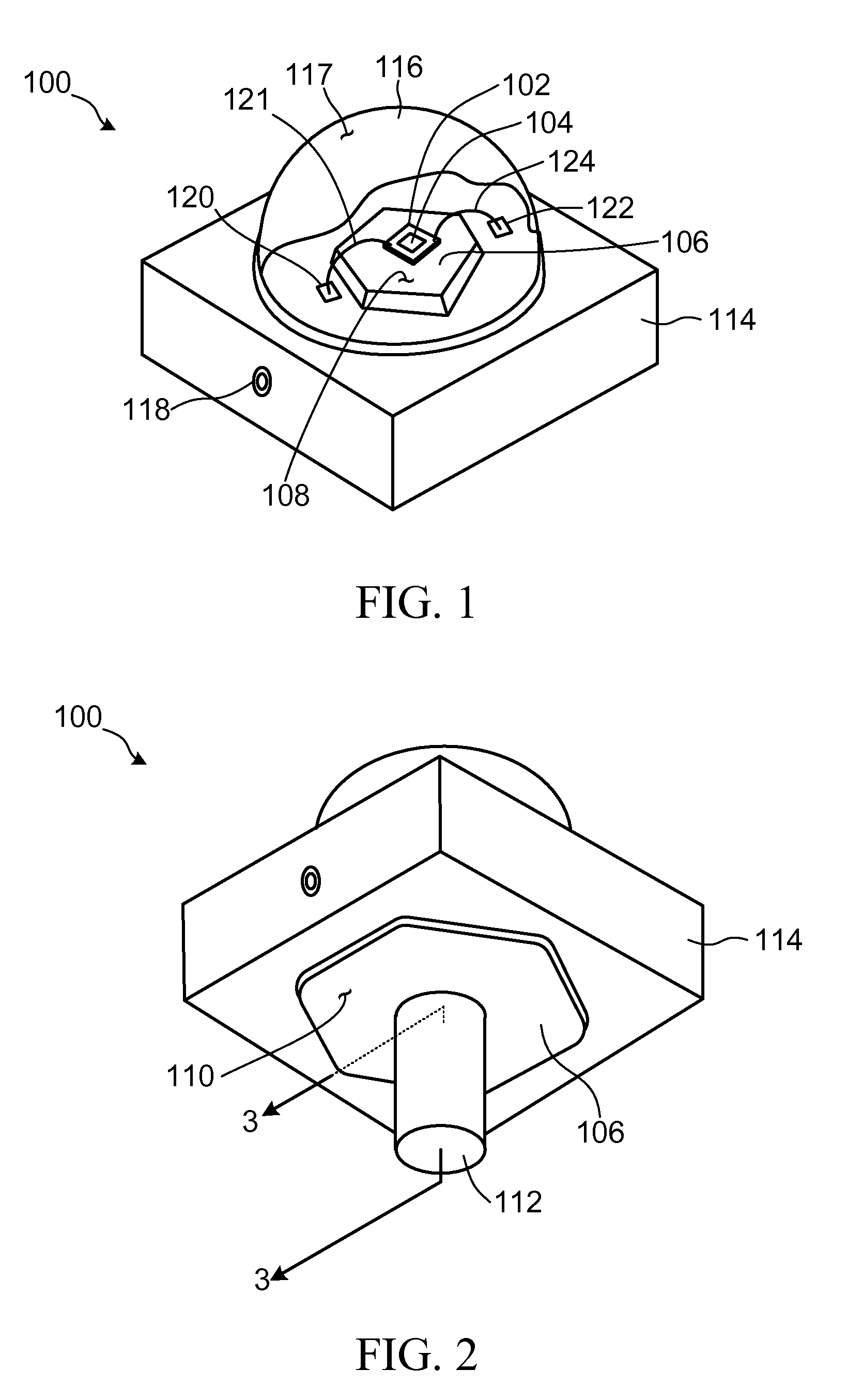
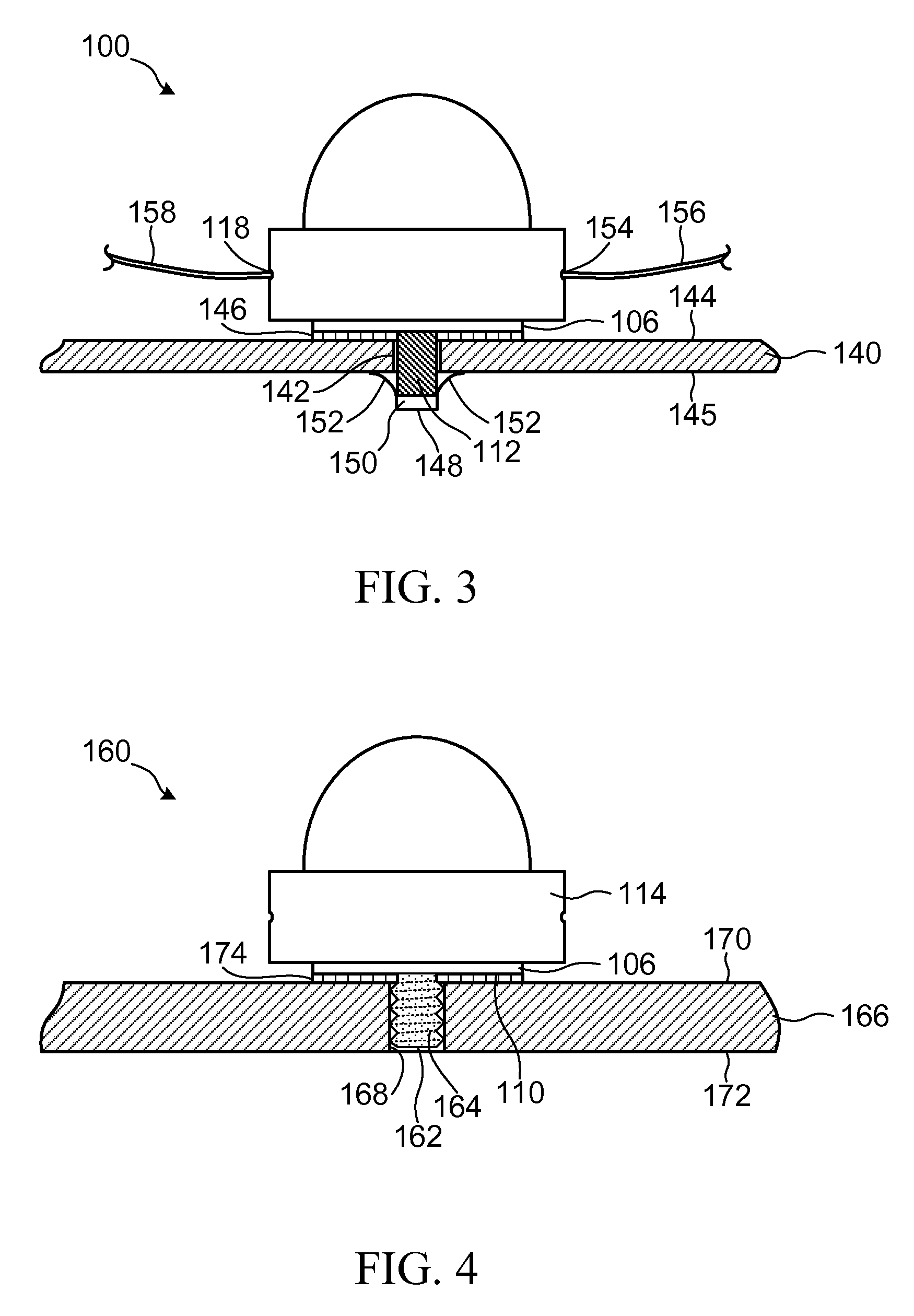
[0061]An LED apparatus according to a first embodiment of the invention is shown generally at 100 in FIG. 1 and FIG. 2. Referring to FIG. 1, the LED 100 includes a sub-mount 102 and at least one LED die 104 mounted on the sub-mount. The sub-mount 102 may comprise ceramic or silicon material, for example. The LED 100 also includes a thermally conductive slug 106 having first and second areas 108 and 110. The first area 108 is thermally coupled to the sub-mount 102. The slug 106 also includes a post 112 protruding outwardly from the second area 110. In general, the post 112 is operably configured to be received in an opening in a heat sink (not shown in FIG. 1) to secure the LED apparatus to the heat sink while causing said second area to be thermally coupled to the heat sink. The heat sink may be a metal or alloy plate or fixture to which the LED 100 is to be mounted, for example. The post 112 and slug 106 may be formed together as a unitary body of thermally conductive material, suc...


PUM

PropertyMeasurementUnit
pressureaaaaaaaaaa
currentaaaaaaaaaa
thermally conductiveaaaaaaaaaa

Abstract

A light emitting diode (LED) apparatus for mounting to a heat sink having a front surface with an opening therein is disclosed. The apparatus includes a sub-mount, at least one LED die mounted on the sub-mount, and a thermally conductive slug having first and second areas. The first area is thermally coupled to the sub-mount and the second area has a post protruding outwardly therefrom. The post is operably configured to be received in the opening in the heat sink and to secure the LED apparatus to the heat sink such that the second area is thermally coupled to the front surface of the heat sink. Other embodiments for mounting an LED apparatus utilizing adhesive thermally conductive material, spring clips, insertion snaps, or welding are also disclosed.

Description

BACKGROUND OF THE INVENTION[0001]1. Field of Invention[0002]This invention relates generally to light emitting diodes (LEDs) and more particularly to mounting LEDs to a heat sink.[0003]2. Description of Related Art[0004]Light Emitting Diodes (LED) have generally been regarded as electronic components and as such have generally been mounted to printed circuit boards (PCB) using various soldering techniques, such as reflow soldering of surface mount packages, for example.[0005]Advances in LED technology have lead to improved optical efficiency at lower manufacturing cost, and higher power LEDs are now available for use in general illumination applications, such as household and commercial lighting. Such applications have established a need for simple, low-cost mounting solutions for LEDs. Soldering may not be a suitable mounting and / or connection solution for lighting industries, which have traditionally relied on relatively low-tech connection and mounting technologies. Introducing s...

Claims


Application Information

Patent Timeline
Patent Type & Authority Patents(United States)
IPC IPC(8): F21V29/00
CPCF21K9/00F21V17/164F21V29/2212F21V3/02F21V29/20F21V19/001F21V29/004F21Y2101/02Y10T29/49826F21Y2115/10F21V29/70F21K9/20F21V29/74F21K9/69F21S2/005F21V17/101F21V23/02
Inventor ZHANG, LISTERANKA, FRANK M.WALL, JR., FRANK J.KMETEC, JEFFWEEKAMP, JOHANNES WILHELMUS
Owner LUMILEDS
Why Eureka
Try Eureka