Heatsink apparatus

a heatsink and apparatus technology, applied in mechanical apparatus, machines/engines, liquid fuel engines, etc., can solve the problems of insufficient heatsink cooling insufficient heatsink air cooling, and decline in reliability of impeller bearing structures, so as to improve overall cooling efficiency and maintain the temperature of heat-generating electronic components. , the effect of low thermal resistan

Inactive Publication Date: 2006-08-03
PANASONIC CORP
View PDF5 Cites 70 Cited by
  • Summary
  • Abstract
  • Description
  • Claims
  • Application Information

AI Technical Summary

Benefits of technology

[0015] The present invention is provided to address the above-described problems. A purpose of the present inventor is to provide a heatsink apparatus that has low thermal resistance on a pump side face and thereby improves overall cooling efficiency and maintains a temperature of a heat-generating electronic component low.

Problems solved by technology

Due to the heat increase, temperatures at contact points of the electronic components surpass an operating temperature range, resulting in more than a few malfunctions of the electronic components.
It is thus a critical issue to maintain the temperatures of the electronic components within the operating temperature range so that the electronic components function properly.
Conventional air-cooling using a heatsink alone, however, is insufficient to cool the heat-generating electronic components.
However, the heatsink apparatus disclosed in Related Art 1, in which a coolant flows through the center of an impeller 302 toward a heat-generating component 303, has the following problems: a complex impeller bearing structure declines reliability; low rigidity of the impeller bearing causes noise or declines reliability; and resistance of the coolant running through a small hole at the center of the impeller causes difficulty in ensuring flow rate of the coolant, thus impeding improvement in cooling performance.
However, the conventional heatsink apparatus has low heat transfer efficiency on an outer peripheral side away from the central portion, thus falling short of achieving highly efficient heat transfer across the pump.

Method used


Image

  • Heatsink apparatus
  • Heatsink apparatus
  • Heatsink apparatus

Examples


first embodiment

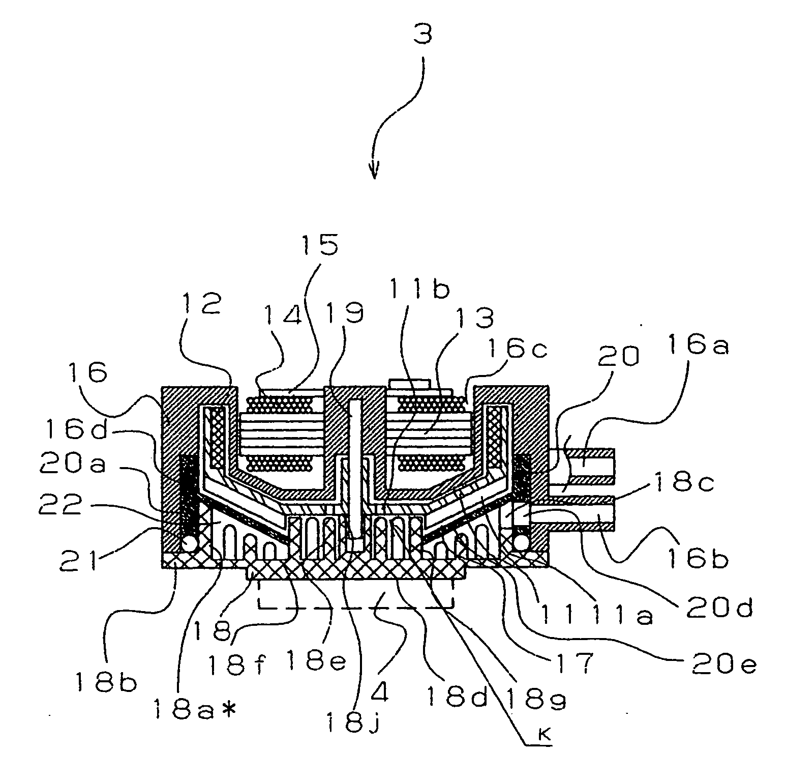
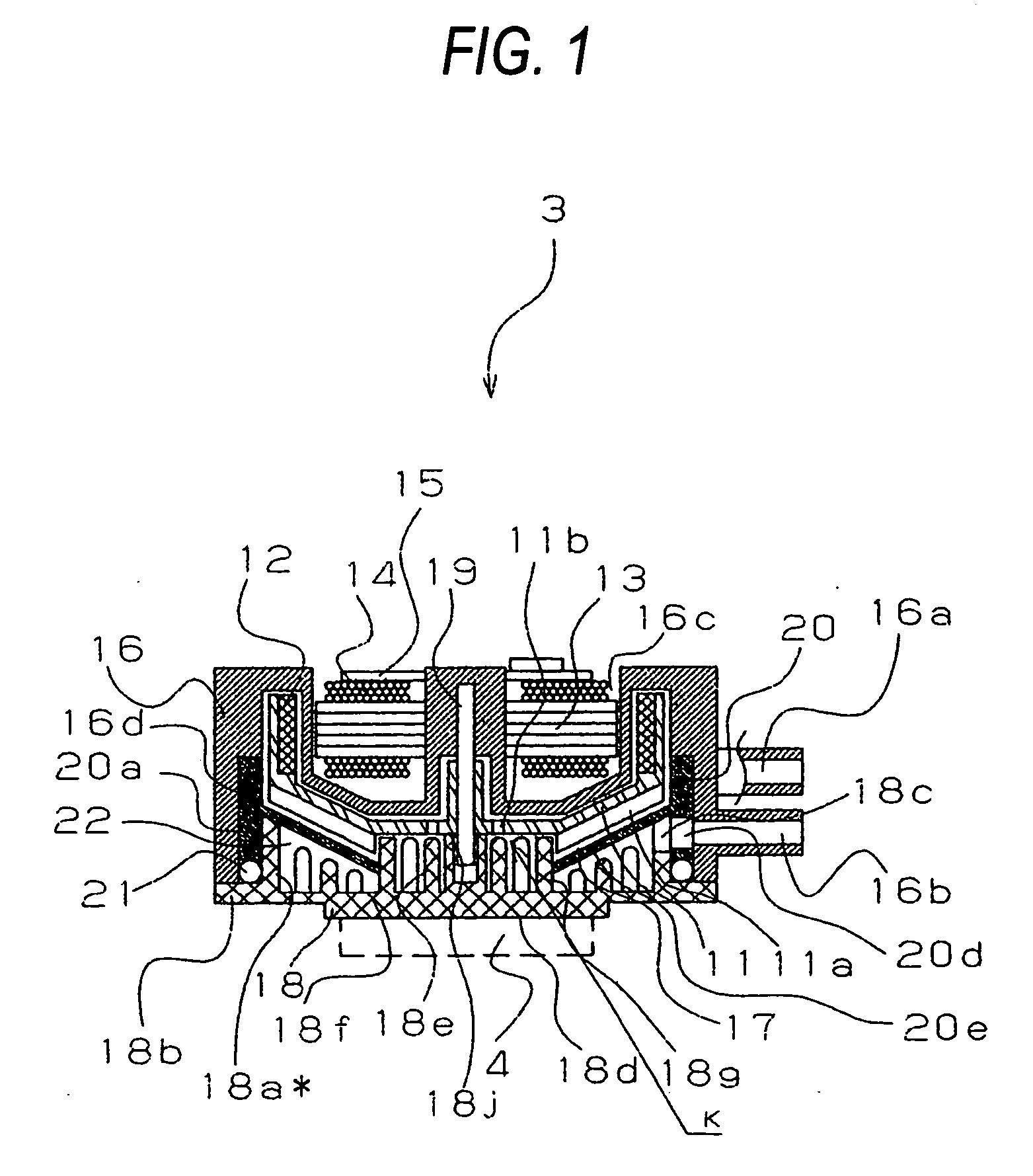
[0037] A centrifugal pump in a heatsink apparatus according to a first embodiment of the present invention is described below. FIG. 1 is a cross-sectional view of the centrifugal pump in the heatsink apparatus according to the first embodiment of the present invention; FIG. 2 is an exploded cross-sectional view of the centrifugal pump in the heatsink apparatus according to the first embodiment of the present invention; FIGS. 3 to 5 are perspective views of a lower casing according to the first embodiment of the present invention; FIG. 6 is a perspective view of a ring-shaped sealing member as a single unit according to the first embodiment of the present invention; and FIG. 7 illustrates a flow direction of a coolant in the centrifugal pump according to the first embodiment of the present invention. An overall structure of an electronic device having the heatsink apparatus according to the first embodiment is the same as that in the conventional art, thus FIGS. 16 and 17 are also re...

second embodiment

[0059] A centrifugal pump in a heatsink apparatus according to a second embodiment of the present invention is described below. FIG. 8 is a cross-sectional view of the centrifugal pump in the heatsink apparatus according to the second embodiment of the present invention; FIG. 9 is an exploded cross-sectional view of the centrifugal pump in the heatsink apparatus according to the second embodiment of the present invention; FIGS. 10 and 11 are perspective views of a lower casing according to the second embodiment of the present invention; FIG. 12 is a perspective view of a ring-shaped sealing member as a single unit according to the second embodiment of the present invention; and FIG. 13 illustrates a flow direction of a coolant in the centrifugal pump according to the second embodiment of the present invention. An overall structure of an electronic device having the heatsink apparatus according to the second embodiment is the same as that in the conventional art, thus FIGS. 16 and 17...


PUM


Abstract

A heatsink apparatus has a radiator and a centrifugal pump in a closed circulation channel for circulating a coolant, wherein the centrifugal pump contacting a heat-generating component dissipates heat from the heat-generating component through heat exchange with the coolant. The centrifugal pump includes: a lower casing provided with a contact surface that contacts the heat-generating component; an upper casing; a ring-shaped sealing member provided between the lower and upper casings so as to form a round heat transfer chamber between the ring-shaped sealing member and the lower casing and to form a pump chamber that houses an impeller between the ring-shaped sealing member and the upper casing; a guiding member provided protruding on the lower casing to make the round heat transfer chamber a circulation channel; and the round heat transfer chamber connecting to a through-hole formed in a central portion of the ring-shaped sealing member.

Description

BACKGROUND OF THE INVENTION [0001] 1. Field of the Invention [0002] The present invention relates to a heatsink apparatus that circulates a coolant to cool heat-generating semiconductors, including a micro processing unit (hereinafter referred to as an MPU) used in a personal computer and the like, and other electronic components having heat-generating portions. [0003] 2. Description of Related Art [0004] Recent electronic devices include highly integrated electronic components and generate high operating clock frequencies, thereby producing a larger amount of heat from the electronic components. Due to the heat increase, temperatures at contact points of the electronic components surpass an operating temperature range, resulting in more than a few malfunctions of the electronic components. It is thus a critical issue to maintain the temperatures of the electronic components within the operating temperature range so that the electronic components function properly. [0005] Convention...

Claims


Application Information

Patent Timeline
Patent Type & Authority Applications(United States)
IPC IPC(8): F04D29/58
CPCF04D13/0673F04D29/588H01L23/473H01L2924/0002H01L2924/00
Inventor MANABE, SEIJISATO, KAORUKOHNO, HARUHIKO
Owner PANASONIC CORP
Why Eureka
Try Eureka