Valve which reacts as a function of pressure, especially for a vibration damper

a valve and pressure technology, applied in the field of valves, can solve the problems of relatively high thermal load of known valves, difficult to adjust valves, and difficult to achieve compressed air feed to valves,

Inactive Publication Date: 2001-10-23
ZF FRIEDRICHSHAFEN AG
View PDF20 Cites 69 Cited by
  • Summary
  • Abstract
  • Description
  • Claims
  • Application Information

AI Technical Summary

Problems solved by technology

One problem is that it is necessary to effectively prevent any leak at the pressure intensifier, originating from the pressure connection, that can cause maladjustment of the valve.
In addition, this known valve has a relatively high thermal load.
Therefore, the compressed-air feed to the valve may be achieved only with a relatively high constructional outlay, since commercially available plastic hoses would scorch under the high thermal load.
Metal tubes cannot be used, or can be used only under certain conditions, in the application of the valve to a vibration damper, since the vibration damper executes relatively large springing movements, which load the metal tube.
Although the inflow restrictor permits compressed air which flows into the low-pressure chamber as leakage air to escape from the latter and ensures that no compressive force builds up on the intensifier in the low-pressure chamber, it is nevertheless impossible for spray water or dust to penetrate unimpeded into the valve.

Method used


Image

  • Valve which reacts as a function of pressure, especially for a vibration damper
  • Valve which reacts as a function of pressure, especially for a vibration damper
  • Valve which reacts as a function of pressure, especially for a vibration damper

Examples


Embodiment Construction

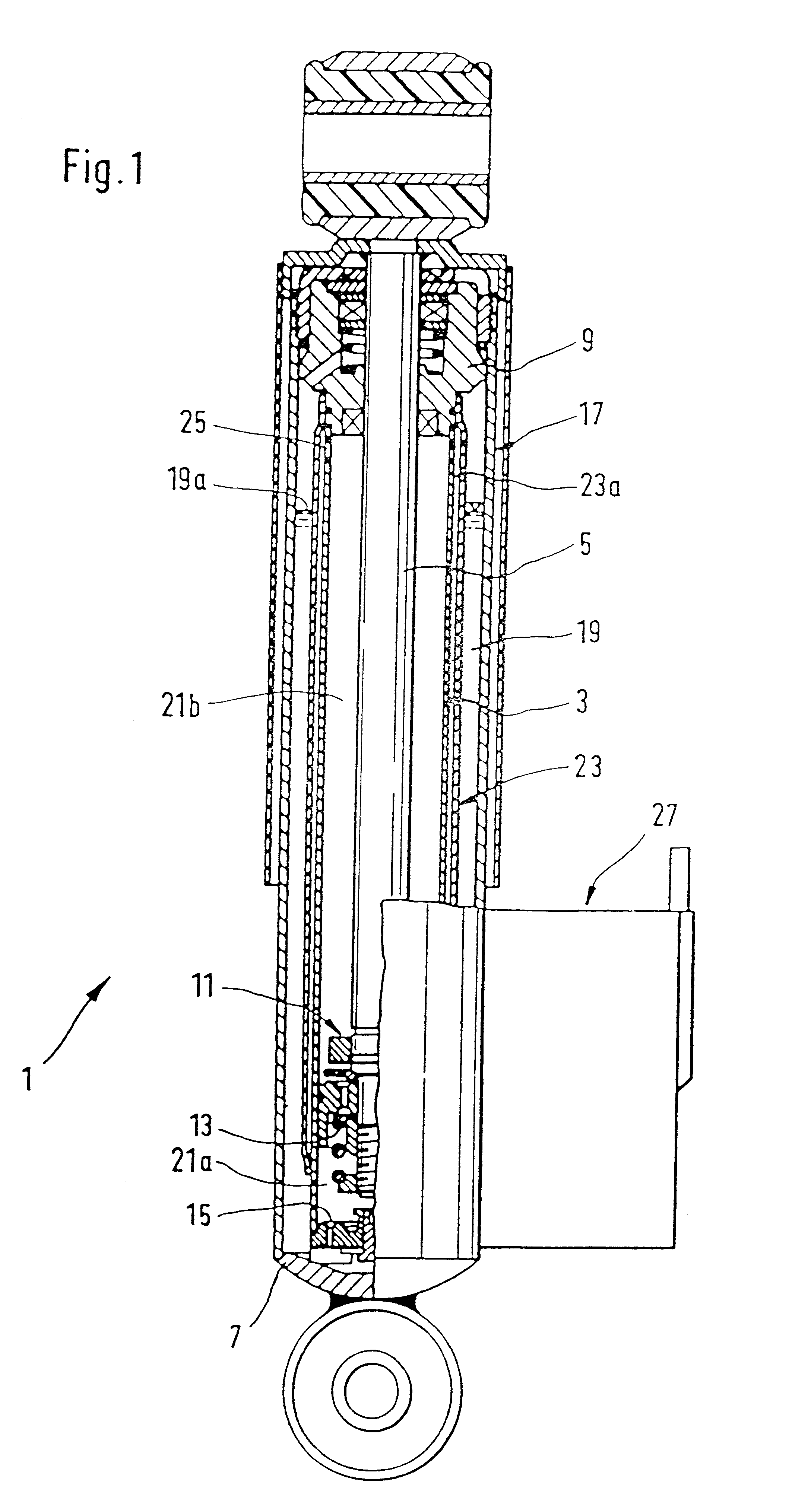
FIG. 1 illustrates a vibration damper 1 having a cylinder 3 in which a piston rod 5 is arranged so as to move axially. The cylinder 3 is closed off at the bottom by a base 7. The piston rod 5 exits the upper end of the cylinder through a guiding and sealing unit 9. Within the cylinder 3, a piston unit 11 having a piston valve arrangement 13 is fixed to the piston rod 5. The base 7 of the cylinder 3 comprises a bottom valve arrangement 15. The cylinder 3 is covered by a container tube 17. An annular chamber is formed between the container tube 17 and the cylinder 1 which represents a balancing chamber. The space within the cylinder 3 is subdivided by the piston unit 11 into a first working chamber 21a and a second working chamber 21b. The first and second working chambers 21a and 21b are filled with pressurized liquid. The balancing chamber 19 is filled up to a level 19a with liquid and above this is filled with gas. Within the balancing chamber 19, a first line section, namely a hig...


PUM


Abstract

A pressure operated valve is provided including an adjusting device, a spring and a vent connection. The adjusting device is axially movably arranged in a pressure chamber defined in the valve and comprises a valve body and a pressure intensifier. A space between the valve body and valve face defines a valve passage cross section. The spring is operatively arranged for holding the pressure intensifier in a floating arrangement in the pressure chamber. The pressure intensifier has a first side exposed to a pressure in the pressure connection opening and a second side facing away from the pressure connection opening. The second side of the pressure intensifier and the adjusting device define a low pressure chamber within the pressure chamber. The vent connection is an inflow restrictor arranged between the lower pressure chamber and a space having a lower pressure than the low pressure chamber.

Description

1. Field of the InventionThe invention relates to a valve having a pressure dependent reaction.2. Description of the Related ArtA valve that reacts as a function of pressure for an adjustable vibration damper is disclosed in DE 44 01 393 C1 and comprises a piston rod axially movably arranged in a cylindrical tube filled with damping liquid. The cylindrical tube has a connection to the pressure-dependent valve, which is driven by an adjusting device to which pressure is applied, the adjusting device having a valve body which is axially movable and is driven by a pressure intensifier mounted so as to float in a pressure chamber. The pressure intensifier is supported by at least one spring which prestresses the pressure intensifier and determines the steepness of an opening characteristic of said valve at given valve cross sections. One problem is that it is necessary to effectively prevent any leak at the pressure intensifier, originating from the pressure connection, that can cause m...

Claims


Application Information

Patent Timeline
Patent Type & Authority Patents(United States)
IPC IPC(8): F16F9/46F16F9/44F16F9/34
CPCF16F9/46F16F2230/183
Inventor HEINZ, NORBERTKUHNEL, JOACHIMKUTSCHE, THOMASMANGER, THOMASASSIIOFF, THORSTENHEYN, STEFFENWIRTH, ALFRED
Owner ZF FRIEDRICHSHAFEN AG
Why Eureka
Try Eureka