Bone drill for centrum

A technology of bone drill and vertebral body, which is applied in the field of bone drill for vertebral body, to achieve significant progress and highlight the effect of substantive features

Inactive Publication Date: 2013-06-12
邵卫星
View PDF8 Cites 5 Cited by
  • Summary
  • Abstract
  • Description
  • Claims
  • Application Information

AI Technical Summary

Problems solved by technology

[0002] In the prior art, the closest technical solution to this application is the vertebral bone drill in use. The drill rods of the existing vertebral body drills are all rigid and cannot be bent. Therefore, the drilling direction of the bone drill can only be The linear direction of the axis of the drill rod, however, ...

Method used


Image

  • Bone drill for centrum

Examples


Embodiment Construction

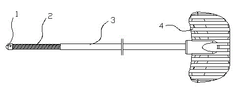
[0008] In order to clearly illustrate the technical features of the solution, the solution will be described below through a specific implementation mode combined with the accompanying drawings.

[0009] As can be seen from the accompanying drawings, the bone drill for the vertebral body of this program includes a drill bit 1, a drill rod 3 and a drill handle 4. Drill rod 2, the length of described soft drill rod 2 is between 15-40 millimeters, and the length of the soft drill rod 2 that this program specific implementation mode adopts is 30 millimeters. The soft drill rod 2 is a soft drill rod with a flexible shaft structure. The soft drill rod 2 of the flexible shaft structure is made of stainless steel.

[0010] The present invention is not limited to the above-mentioned specific implementation methods, and changes, modifications, additions or substitutions made by those skilled in the art within the essential scope of the present invention should also fall within the prot...


PUM

PropertyMeasurementUnit
Lengthaaaaaaaaaa
Lengthaaaaaaaaaa

Abstract

The invention provides a technical scheme of a bone drill for centrum. The bone drill comprises a drill bit, a drill rod and a drill handle, and is characterized in that a flexible drill rod is fixedly connected between the drill bit and the drill rod, and the length of the flexible drill rod is within a range of 15-40mm. The bone drill is specifically characterized in that the flexible drill rod is of a flexible shaft structure. The flexible drill rod with the flexible shaft structure is made of a stainless steel material. The length of the flexible drill rod is 30mm. According to the bone drill for centrum, a rigid drill rod is changed into the flexible drill rod, one section, behind the drill bit, of the flexible drill rod can be bent. The flexible drill rod is capable of changing a drilling direction of the drill bit, and a channel is drilled through according to a direction required by an operation.

Description

technical field [0001] The invention relates to an orthopedic surgical instrument, in particular to a bone drill for vertebral bodies. Background technique [0002] In the prior art, the closest technical solution to this application is the vertebral bone drill in use. The drill rods of the existing vertebral body drills are all rigid and cannot be bent. Therefore, the drilling direction of the bone drill can only be The linear direction of the axis of the drill rod, however, some operations require that the channel opened by the bone drill is not in the axial direction of the working sleeve, but on one side of the axis of the working sleeve, and the drill rod of the bone drill needs to be bent to get through. The vertebral body bone drill can't be realized, and this is the weak point that the prior art exists. Contents of the invention [0003] The technical problem to be solved by the present invention is to provide a technical proposal for a bone drill for the vertebra...

Claims


Application Information

Patent Timeline
IPC IPC(8): A61B17/16
Inventor 唐海李维铭杨文州邵卫星
Owner 邵卫星
Why Eureka
Try Eureka