Supercharge Your Innovation With Domain-Expert AI Agents!

Cutting tool

A technology of cutting tools and blades, which is applied in the field of setting screw holes on cutting tools, and can solve problems such as screw holes and new screws not being able to cooperate normally, tools being scrapped, etc.

Inactive Publication Date: 2013-06-12
苏州维赛克阀门检测技术有限公司
View PDF8 Cites 0 Cited by
  • Summary
  • Abstract
  • Description
  • Claims
  • Application Information

AI Technical Summary

Problems solved by technology

[0002] In the existing matching design of screws and screw holes, design engineers usually set the screw holes as blind holes. Therefore, when the screw is screwed into the screw hole, sometimes the screw will be broken due to excessive force. The screw in the hole cannot be removed, which will cause the screw hole and the new screw to not cooperate normally, resulting in the scrapping of the whole or part of the tool

Method used


Image

  • Cutting tool
  • Cutting tool
  • Cutting tool

Examples


Embodiment Construction

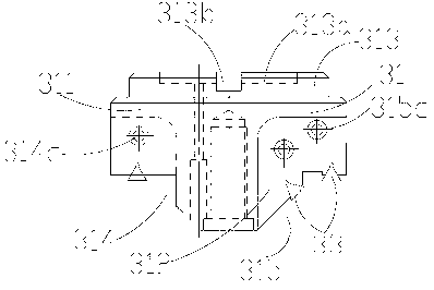
[0020] The cutting tool 100 of the present invention will be described in detail below with reference to the accompanying drawings.

[0021] see figure 1 As shown, the cutting tool 100 includes: an installation body (not numbered), a cavity formed by the mating connection of an upper cavity 2 and a lower cavity 1, a cutting head 3 installed at one end of the installation body, sleeved on the upper The positioning flange 4 on the cavity 2 and close to the cutting head 3, the motor connecting shaft (unlabeled) installed in the upper cavity 2, and the motor connection shaft (not labeled) installed on the cavity and located at the opposite ends of the cavity with the cutting head 3 The motor 5, and the motor connection plate 6 for installing the motor 5 to the cavity between the positioning flange 4 and the motor 5, the motor connection plate 6 is connected to the end of the upper cavity 2, and the motor 5 passes through the motor The connection plate 6 and the motor connection s...


PUM


Abstract

The invention relates to a cutting tool, which comprises a cutting head. The cutting head comprises a head main body with a cylindrical body, a plurality of blades arranged on the head main body and a blade pressing claw for fixedly clamping the blades on the cutting head. The body is symmetrically provided with a pair of notches in a sunken way. Each notch is provided with two sidewalls which are perpendicular to each other. The blade pressing claw is arranged on one sidewall of each of the notches. The blades are fixedly arranged on one sidewall by the blade pressing claw. Through holes for arranging the blade pressing claw are formed in the sidewalls, penetrate through the body, and extend to the outer lateral surface of the body. The cutting tool has the beneficial effects that by the through holes, a screw broken in a screw hole can be conveniently taken out.

Description

technical field [0001] The invention relates to a cutting tool, in particular to an arrangement of screw holes on the cutting tool. Background technique [0002] In the existing matching design of screws and screw holes, design engineers usually set the screw holes as blind holes. Therefore, when the screw is screwed into the screw hole, sometimes the screw will be broken due to excessive force. The screw in the hole cannot be taken out, so that the screw hole and the new screw cannot be properly matched, and the whole or part of the tool is scrapped. Contents of the invention [0003] Aiming at the deficiencies of the prior art, the technical problem to be solved by the present invention is to provide a cutter head body in which the screw hole is set as a through hole, and the setting of the through hole is convenient for taking out the broken screw in the screw hole. [0004] In order to solve the above-mentioned technical problems, the technical solution of the present...

Claims


Application Information

Patent Timeline
IPC IPC(8): B23D79/00
Inventor 赵陆军
Owner 苏州维赛克阀门检测技术有限公司
Features
  • R&D
  • Intellectual Property
  • Life Sciences
  • Materials
  • Tech Scout
  • Unparalleled Data Quality
  • Higher Quality Content
  • 60% Fewer Hallucinations
Learn More