Subframe and the car with it

A subframe and automobile technology, applied in the field of subframes and automobiles with it, can solve the problems of lack of buffer energy absorption, small deformation of subframe, and less application, so as to increase the overall rigidity and avoid serious damage. Deformation, the effect of protecting personal safety

Active Publication Date: 2016-01-20
精诚工科汽车系统有限公司
View PDF6 Cites 0 Cited by
  • Summary
  • Abstract
  • Description
  • Claims
  • Application Information

AI Technical Summary

Problems solved by technology

However, since the subframe is made of steel, its weight is heavy, and its fuel economy is not good. From the perspective of cushioning and energy absorption, the deformation of the subframe is small in the event of a frontal collision of the vehicle, so it cannot play the role of cushioning and energy absorption. , the impact force will be directly transmitted to the cab through the sub-frame, threatening the safety of the driver and passengers, and the safety of the whole vehicle is poor
[0004] In some models, in order to improve the collision safety of the vehicle, a buffer energy-absorbing module is added to the front end of the sub-frame. Although this method improves the collision safety of the vehicle to a certain extent, it will inevitably increase the front suspension of the vehicle. Length, affects the layout of the vehicle
[0005] If the subframe is made of aluminum alloy, although it can improve the collision safety, reduce the weight of the vehicle, and obtain better fuel economy, the cost of aluminum alloy materials is too high, so there are few applications

Method used


Image

  • Subframe and the car with it
  • Subframe and the car with it
  • Subframe and the car with it

Examples


Embodiment Construction

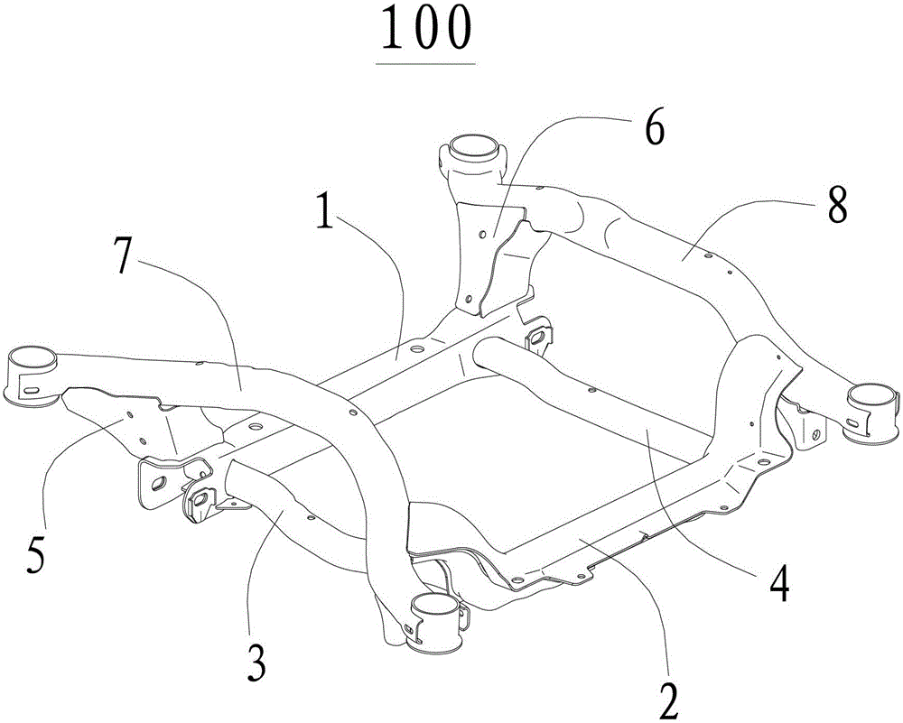
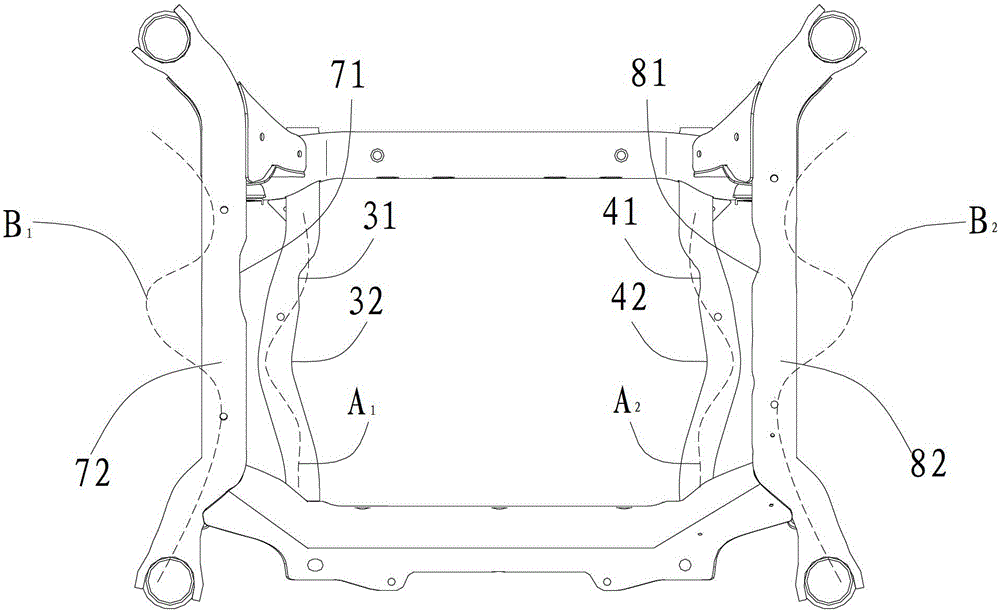
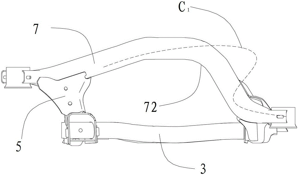
[0047] Embodiments of the present invention are described in detail below, examples of which are shown in the drawings, wherein the same or similar reference numerals designate the same or similar elements or elements having the same or similar functions throughout. The embodiments described below by referring to the figures are exemplary and are intended to explain the present invention and should not be construed as limiting the present invention.

[0048] In describing the present invention, it should be understood that the terms "center", "longitudinal", "transverse", "length", "width", "thickness", "upper", "lower", "front", " Orientation or position indicated by "back", "left", "right", "vertical", "horizontal", "top", "bottom", "inner", "outer", "clockwise", "counterclockwise", etc. The relationship is based on the orientation or positional relationship shown in the drawings, and is only for the convenience of describing the present invention and simplifying the descrip...


PUM


Abstract

The invention discloses an auxiliary frame and an automobile. The auxiliary frame comprises a front cross beam, a rear cross beam, a left lower longitudinal beam, a right lower longitudinal beam, a left connecting part, a right connecting part, a left upper longitudinal beam and a right upper longitudinal beam. A front end and a rear end of the left lower longitudinal beam are respectively fixed onto the front cross beam and the rear cross beam, and a left lower energy absorption structure is arranged on the left lower longitudinal beam. A front end and a rear end of the right lower longitudinal beam are respectively fixed onto the front cross beam and the rear cross beam, and a right lower energy absorption structure is arranged on the right lower longitudinal beam. The left connecting part and the right connecting part are respectively arranged above the front cross beam. A front end and a rear end of the left upper longitudinal beam are respectively fixed onto the left connecting part and the rear cross beam, and a left upper energy absorption structure is arranged on the left upper longitudinal beam. A front end and a rear end of the right upper longitudinal beam are respectively fixed onto the right connecting part and the rear cross beam, and a right upper energy absorption structure is arranged on the right upper longitudinal beam. The auxiliary frame has large rigidity and strength, can well absorb collision energy when automobile is collided directly, the personnel safety of a driver and passengers in a cab is protected, and the safety of the whole automobile is improved.

Description

technical field [0001] The invention relates to the technical field of automobile construction, in particular to an auxiliary frame and an automobile with the same. Background technique [0002] As an important part of the car suspension, the sub-frame of the car is a bridge connecting the body and the wheels. At the same time, the sub-frame can also be used to connect and support the engine, steering system and swing arm. [0003] Considering the vehicle's requirements for handling stability, it is hoped that the greater the stiffness of the suspension, the better. Therefore, the sub-frame of a car is usually stamped and formed by multiple pieces of high-strength steel plates with a thickness of about 2mm. The whole vehicle with this kind of sub-frame has high suspension rigidity and good handling performance. However, since the subframe is made of steel, its weight is heavy, and its fuel economy is not good. From the perspective of cushioning and energy absorption, the de...

Claims


Application Information

Patent Timeline
Patent Type & Authority Patents(China)
IPC IPC(8): B62D21/02
Inventor 王雪峰管艳艳李志强乔君辉齐改霞段红霞刘彦龙董苗静宋永辉
Owner 精诚工科汽车系统有限公司
Why Eureka
Try Eureka