

Pipeline self-locking, clasping and pushing device and usage method thereof
A technology of pushing device and pipeline, which is applied in the directions of pipeline laying and maintenance, pipe/pipe joint/pipe fitting, mechanical equipment, etc., can solve the torsion-pull fracture of the main return drill pipe and the inability to meet the pipeline crossing construction task. , traversal failure, etc.
- Summary
- Abstract
- Description
- Claims
- Application Information
AI Technical Summary
Problems solved by technology
Method used
Image

Examples
Embodiment Construction
[0042] The technical solutions of the various embodiments of the present invention will be clearly and completely described below in conjunction with the accompanying drawings. Apparently, the described embodiments are only some of the embodiments of the present invention, not all of them. Based on the embodiments of the present invention, all other embodiments obtained by persons of ordinary skill in the art without making creative efforts belong to the protection scope of the present invention.
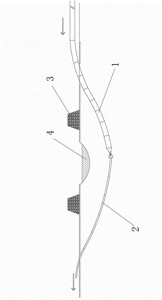
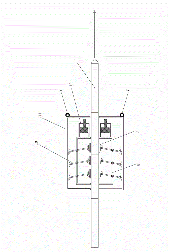
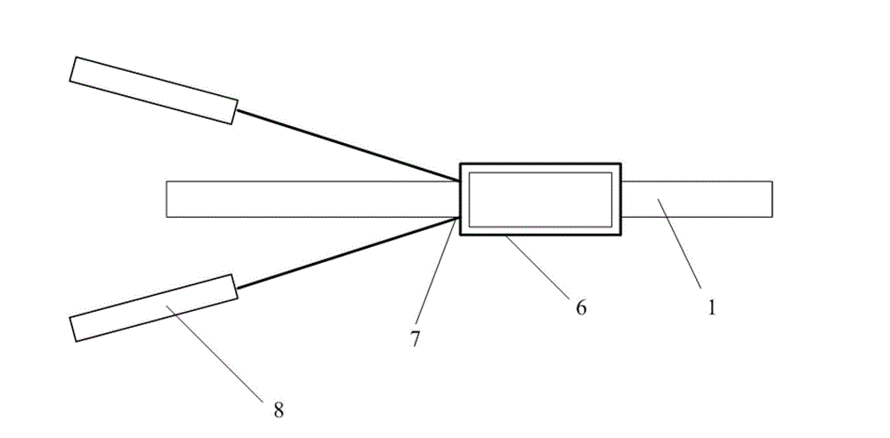
[0043] The invention provides a pipe self-locking push device, which includes more than one push rod, one end of the push rod is provided with a push piece, the push piece is in the shape of an arc, and all the push pieces form a The cylindrical pipe channel into which the pipeline is placed, the other ends of all the push rods are hingedly connected to the outer bracket, the middle parts of all the push rods are hinged to the inner bracket, and the outer brackets on the same side A...
PUM
 Abstract
Description
Claims
Application Information