Wireless energy transfer system

A wireless energy and transfer system technology, applied in electromagnetic wave systems, circuit devices, electrical components, etc., can solve the problem of not providing suitable solutions, and achieve the effect of avoiding radiation

Inactive Publication Date: 2013-06-12
SONY CORP
View PDF5 Cites 32 Cited by
  • Summary
  • Abstract
  • Description
  • Claims
  • Application Information

AI Technical Summary

Problems solved by technology

However, they do not provide a suitable solution to the above problems

Method used


Image

  • Wireless energy transfer system
  • Wireless energy transfer system
  • Wireless energy transfer system

Examples


Embodiment Construction

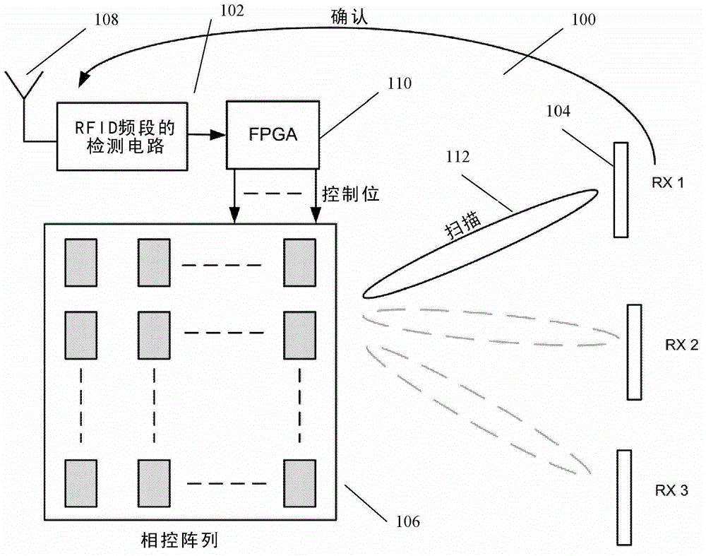
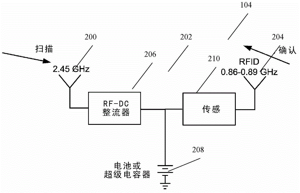
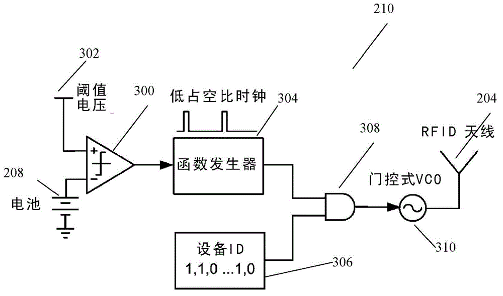
[0037] figure 1 The system 100 shown in is used for wireless energy transfer between a base station 102 and a mobile electronic device 104 . The base station 102 includes a 2.4GHz steerable antenna 106 for transmission and an 860MHz antenna 108 for receipt acknowledgment. A Field Programmable Gate Array (FPGA) 110 acts as a controller. FPGA 110 controls steerable antenna 106 to send a focused burst of radio frequency radiation that is used to scan the area of ​​partition 112 for any devices 104 . Based on any acknowledgments received, FPGA 110 will determine the location of any identified devices 104 . The steerable antenna 106 then focuses continuous radio frequency radiation toward that location to transfer energy to the device 104 . This location is tracked and updated if device 104 moves to another partition.

[0038] The steerable antenna 106 is a phased array with M×N elements. It emits radio frequency energy at 2.45GHz and has a range of several meters. The covera...


PUM


Abstract

The invention relates to a wireless energy transfer system, comprising: a transmitter configured to beam scan RF radiation across a plurality of sectors at a first frequency, a receiver storing energy from the RF radiation, and sending acknowledgements at a second frequency, the first frequency being significantly different from the second frequency, and a controller configured to direct wireless energy transfer from the transmitter substantially at the receiver based on the acknowledgements.

Description

technical field [0001] The present invention relates to a wireless energy transfer system. Background technique [0002] As mobile electronic devices become more pervasive, the ease and flexibility of charging the mobile device's battery becomes more important. Typically, most prior art devices use a mains connected converter that is hardwired to the mobile device to provide low voltage direct current for charging. [0003] An alternative to wired charging is wireless charging. Examples of existing technologies for wireless energy transfer include induction, resonant coupling, electromagnetic radiation, and laser light. Induction is only useful if the device is in close proximity, such as a wireless dock that charges an electric toothbrush, or a transformer. Resonant coupling is used at medium distances, such as in some RFIDs and smart cards. Since efficiency decreases significantly with distance, a high degree of directivity is required for larger distances. Longer dis...

Claims


Application Information

Patent Timeline
Patent Type & Authority Applications(China)
IPC IPC(8): H02J17/00
CPCH02J50/23H02J50/27H02J50/402H02J50/90
Inventor 夏晶晶吴伟鹏增田久
Owner SONY CORP
Why Eureka
Try Eureka