Fire emergency lighting control circuit

A technology for controlling circuits and emergency lighting, applied in lighting devices, electric lamp circuit layout, electric light sources, etc., can solve problems such as lamp extinguishing, emergency lighting system lamps failing to light normally, and failure to ensure the normal use of backup lighting for emergency evacuation of personnel, etc. Achieve the effect of ensuring the work illuminance and ensuring the illuminance requirements

Active Publication Date: 2015-08-26
JIANGSU PROVINCIAL ARCHITECTURAL D&R INST
View PDF4 Cites 0 Cited by
  • Summary
  • Abstract
  • Description
  • Claims
  • Application Information

AI Technical Summary

Problems solved by technology

[0002] The fire emergency lighting lamps are controlled by ordinary single-control switches. Even if the reliability of the power supply of the power distribution system is guaranteed, when the switch is turned off, the lamps are extinguished.
At this time, once a fire accident occurs, the emergency lighting system lamps cannot be normally lit, and the emergency evacuation of personnel in the event of a fire and the normal use of backup lighting for firefighters and places that need to continue working in the building cannot be guaranteed.

Method used


Image

  • Fire emergency lighting control circuit
  • Fire emergency lighting control circuit
  • Fire emergency lighting control circuit

Examples


no. 1 example

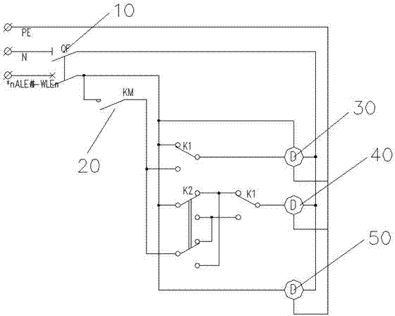
[0023] image 3 It is the circuit diagram of the fire emergency lighting control circuit of the first specific embodiment of the present invention, combined below image 3 The first specific embodiment of the present invention is described in detail:

[0024] The fire emergency lighting control circuit of the first specific embodiment of the present invention includes a miniature circuit breaker 10 for the outlet of the lighting distribution box, a fire alarm output linkage control contactor 20, a single-control emergency lighting lamp 30, a double-control emergency lighting lamp 40 and an evacuation indicator Light 50, fire alarm output linkage control contactor 20 is located in the lighting distribution box, single-control emergency lighting 30, double-control emergency lighting 40 and evacuation indicator light 50 are all connected to the normal power line and fire emergency power line, One end of the single-control emergency lighting lamp 30 is connected to the double-con...

no. 2 example

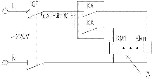
[0027] Figure 4 It is the circuit diagram of the fire emergency lighting control circuit of the second specific embodiment of the present invention, combined below Figure 4 The second specific embodiment of the present invention is described in detail:

[0028] The fire emergency lighting control circuit of the second specific embodiment of the present invention includes BA linkage output 12, fire alarm output linkage control contactor 13, lighting distribution box outgoing line isolation switch 11, centralized control emergency lighting dome light 14 and evacuation indicator light 15, The BA linkage output 12 and the fire alarm output linkage control contactor 13 are located in the lighting distribution box, and the centralized control emergency lighting dome light 14 and evacuation indicator light 15 are connected to the normal power line and the fire emergency power line.

[0029] The fire emergency lighting control circuit of the second specific embodiment of the presen...


PUM


Abstract

The invention discloses a fire emergency lighting control circuit. The fire emergency lighting control circuit comprises a fire alarm output linkage control contactor, wherein the fire alarm output linkage control contactor comprises a fire automatic alarm linkage output contact and an intermediate relay contact part; the fire automatic alarm linkage output contact is controlled by a control module and an intermediate relay; one end of the control module is connected with a loop bus and a power bus, and the other end of the control module is connected with the intermediate relay; and the intermediate relay contact part can be communicated with a plurality of alternating current contactors. According to the fire emergency lighting control circuit, when a fire occurs, an emergency lighting lamp can acquire power from an emergency lighting distribution box regardless of the state of an emergency lighting lamp control switch, so that the emergency lighting lamp can be instantly turned on for fire emergency. A requirement on illumination for people safe evacuation during the occurrence of the fire is met, and the working illumination of a working scene on which firefighters continuously perform rescue operation during the occurrence of the fire is ensured.

Description

technical field [0001] The invention relates to the technical field of control circuits, in particular to a fire emergency lighting control circuit suitable for starting emergency lighting in emergency situations. Background technique [0002] The fire emergency lighting lamps are controlled by ordinary single-control switches. Even if the reliability of the power supply of the power distribution system is guaranteed, when the switch is turned off, the lamps go out. At this time, once a fire accident occurs, the emergency lighting system lamps cannot be normally lit, and the emergency evacuation of personnel during a fire and the normal use of backup lighting for firefighters and places that need to continue working in the building cannot be guaranteed. Contents of the invention [0003] The purpose of the present invention is to provide a fire emergency lighting control circuit that can obtain power from the emergency lighting distribution box to ensure that the emergency...

Claims


Application Information

Patent Timeline
Patent Type & Authority Patents(China)
IPC IPC(8): H05B37/02
Inventor 毛丽伟
Owner JIANGSU PROVINCIAL ARCHITECTURAL D&R INST
Why Eureka
Try Eureka