Arc protection switch

An anti-arc and switching technology, applied in the electrical field, can solve problems such as affecting the service life, and achieve the effect of prolonging the service life, eliminating the influence and improving the safety performance.

Pending Publication Date: 2021-11-09
ZHEJIANG CHINT BUILDING ELECTRICS
View PDF0 Cites 0 Cited by
  • Summary
  • Abstract
  • Description
  • Claims
  • Application Information

AI Technical Summary

Problems solved by technology

[0004] Therefore, the technical problem to be solved by the present invention is to overcome the problem that the arc shield in the prior art only blocks the high-temperature arc inside, and tries not to let the high-tem

Method used


Image

  • Arc protection switch
  • Arc protection switch
  • Arc protection switch

Examples


Embodiment

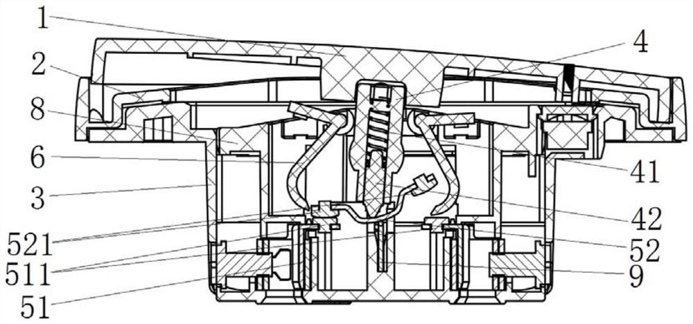
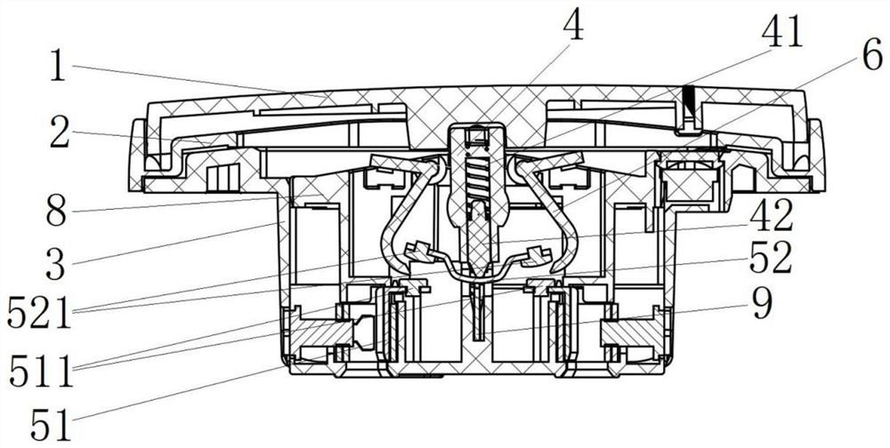
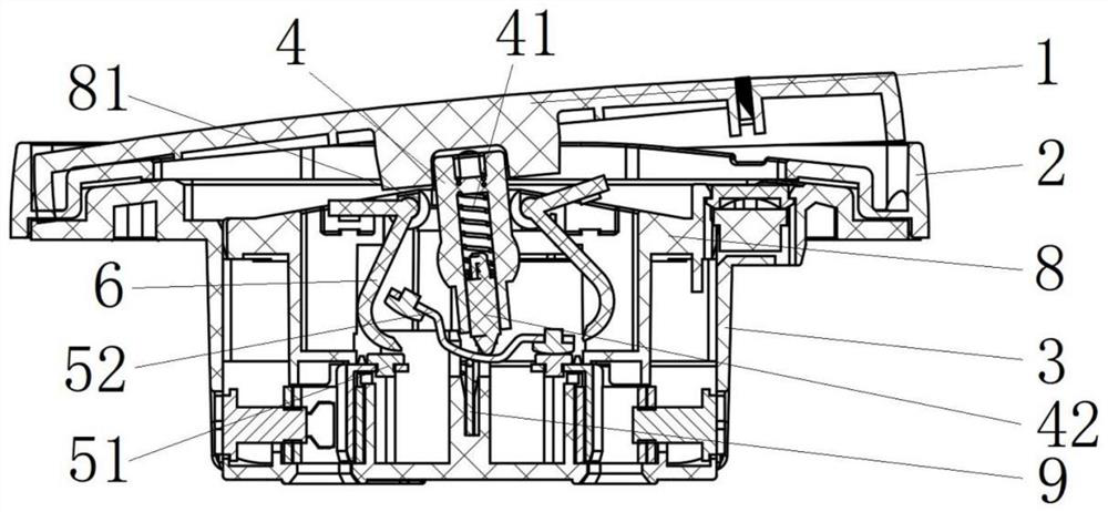
[0046] like Figure 1 to Figure 14 The shown arc-proof switch includes a cover plate 1 , a panel 2 , an installation base 3 , a button 4 , a contact assembly, a barrier 6 , a reset member, a pressure plate 8 and a conductive member assembly 9 . Wherein, the cover plate 1 is set on the panel 2; the panel 2 is set on the installation base 3; A spring 41 and a push rod 42 are provided in turn; the contact assembly is located in the installation base 3, the contact assembly includes a moving contact assembly 52 and a static contact assembly 51, and the moving contact assembly 52 and the static contact assembly 51 are along the Figure 1 to Figure 4 The upper and lower directions are opposite to each other, the push rod 42 abuts against the moving contact assembly 52 ; the button 4 passes through the pressing plate 8 ; the conductive element assembly 9 is connected to the moving contact assembly 52 .

[0047] The barrier member 6 in this embodiment is set to rotate, the barrier memb...


PUM


Abstract

The invention discloses an arc protection switch, which comprises a cover plate, a mounting base, a button, a contact assembly located in the mounting base and comprising a moving contact assembly and a static contact assembly, and a blocking piece rotatably arranged and comprising a driving part and a blocking part, the driving part is arranged close to the button, and the blocking part is arranged close to the contact assembly. When the cover plate is pressed and acts on the cover plate, the cover plate drives the button to rotate, the button acts on the driving part to enable the blocking piece to rotate, and the blocking part moves to a position between the movable contact of the movable contact assembly and the static contact of the static contact assembly and achieves conversion from the on state to the off state of the movable contact of the movable contact assembly and the static contact of the static contact assembly. Through the arrangement of the blocking piece, when the cover plate is pressed, the button acts on the driving part to enable the blocking part to move to the position between the movable contact and the static contact which are switched from the on state to the off state, so that the high-temperature electric arc generated by the disconnection of the contacts is cut off by the blocking part to extinguish the high-temperature electric arc.

Description

technical field [0001] The invention and the electrical technical field specifically relate to an arc protection switch. Background technique [0002] With the rapid development of economy and society, the number of electrical equipment used in large-scale electricity-consuming places such as computer rooms, shopping malls, and schools continues to increase, and the task of reducing the energy consumption of these electrical equipment has become very urgent. There are a huge number of DC power equipment in these power places, and most of them use AC power supply. When working, they need to be equipped with AC adapters to convert AC power into DC power to supply DC power equipment. Here The conversion efficiency of the process is usually around 80%. In the DC power supply, when the plug is plugged and pulled out on the DC socket, the air gap between the plug and the conductor of the socket breaks down to generate a high-temperature arc. [0003] In the prior art, an arc shi...

Claims


Application Information

Patent Timeline
IPC IPC(8): H01H23/12H01H23/02H01H9/32
CPCH01H23/12H01H23/02H01H9/32
Inventor 张仕森刘远方张梅陈旭娇张宏文郑立清曹西飞黄敦建
Owner ZHEJIANG CHINT BUILDING ELECTRICS
Why Eureka
Try Eureka