Dynamic flow heater

一种加热器、加热装置的技术,应用在紧凑的流体加热器,连续流动的加热器领域,能够解决比率大、冷的芯子流动等问题,达到有利温度控制特征、小空载时间和/或时间常数的效果

Inactive Publication Date: 2013-06-12
BLECKMANN
View PDF9 Cites 15 Cited by
  • Summary
  • Abstract
  • Description
  • Claims
  • Application Information

AI Technical Summary

Problems solved by technology

Hitherto, the circular cross-sections used for the fluid conduit guiding cores have created problems in that the ratio between the heating contact surface and the fluid volume in the fluid conduit is too large and cold core flow ensues

Method used


Image

  • Dynamic flow heater
  • Dynamic flow heater
  • Dynamic flow heater

Examples


Embodiment Construction

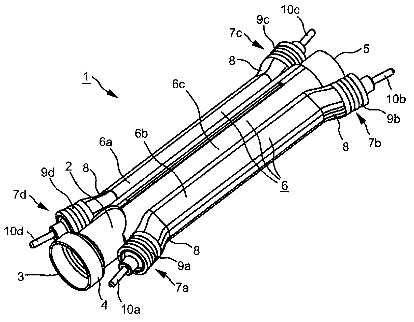
[0076] figure 1 It shows that the basic elements of the fluid connector 1 of the present invention, the metal pipe 2 and the heating device 6, the heating device 6 includes two identical tubular heating elements 6a, 6b and a heat conducting device 6c.

[0077] The metal pipe 2 has an opening 3 in a widened first end portion 4, and the widened first end portion 4 has a cross-sectional enlarged portion compared with other parts of the metal pipe. At the end 5 of the metal pipe 2 opposite to the widened end 4, a sealing plug or end cap 50 can be provided (see Figure 4 , 5, 9), to airtightly and pressure-tightly seal the end.

[0078] in figure 1 The heating device 6 shown in FIG. 6 includes tubular heating elements 6a and 6b and a heat conduction device implemented as a heat conduction plate 6c. The heat conduction plate 6c completely surrounds the metal pipe 2 in the circumferential direction, and the tubular heating elements 6a and 6b are equally spaced along the circumferential di...


PUM


Abstract

A fluid heater of the flow-heater type with a fluid channel having a first fluid channel section (35), at least one substantially cylindrical metal pipe (2), a heating device (6) having preferably two tubular heating bodies (6a, 6b) spaced apart from each other over equidistant circumferential sections of the metal pipe, and a heat-conducting means for the heat-conducting connection to the metal pipe (2), wherein a fluid-guiding core (30) which is made from plastic is arranged in the metal pipe (2), the fluid-guiding core forming the first fluid channel section (35) between the metal pipe and the fluid-guiding core (30), wherein the first fluid channel section (35) runs substantially helically in the form of a groove in an outer surface of the fluid-guiding core,; and wherein the fluid channel has a first fluid connection for fluid supply means and a second fluid connection for fluid removal means, wherein the fluid-guiding core (30) furthermore has a second fluid channel section (34) which is arranged, substantially coaxially, in the interior thereof and is connected in series with the first fluid channel section (35). A fluid connection subassembly can be provided in the region of a first end of the metal pipe (2), said fluid connection subassembly having both the first fluid connection (24a) and the second fluid connection (24b), and therefore fluid is supplied and fluid is removed in the region of the same end sides of the metal pipe (2). A closure stopper (50) is then provided in the region of the second end of the metal pipe (2).

Description

Technical field [0001] The present invention generally relates to fluid heaters, and in particular to continuous flow heaters for household appliances. More specifically, the present invention relates to a compact fluid heater with high heat capacity and small size. Background technique [0002] Various designs and types of fluid heaters for producing hot fluids, especially hot water or steam, are known in the prior art. Household appliances in which fluid heaters are used include steam cleaners, steam irons, and appliances for preparing meals and / or hot beverages, such as coffee machines, espresso machines, milk froth machines, steam boilers, and others. [0003] To some extent at least the element for these devices is that fluid heaters that use electrical energy to generate hot fluid or steam from cold fluids are integrated in compact devices, that is, devices that have restricted internal space. The fluid conduit must also withstand several environmental pressures, especially...

Claims


Application Information

Patent Timeline
Patent Type & Authority Applications(China)
IPC IPC(8): A47J31/54F24H1/16
CPCF24H1/142A47J31/542
Inventor M.赖克尔A.普莱辛格
Owner BLECKMANN
Why Eureka
Try Eureka