
Method for controlling a torque converter clutch device

A clutch device, torque converter technology, applied in the direction of transmission, transmission control, fluid transmission, etc., can solve the driver's discomfort and other problems, and achieve the effect of convenient wear

Active Publication Date: 2016-12-28
ZF FRIEDRICHSHAFEN AG
View PDF13 Cites 0 Cited by
  • Summary
  • Abstract
  • Description
  • Claims
  • Application Information

AI Technical Summary

Problems solved by technology

Such a shift shock can make the driver feel uncomfortable

Method used


Image

  • Method for controlling a torque converter clutch device

Examples


Embodiment Construction

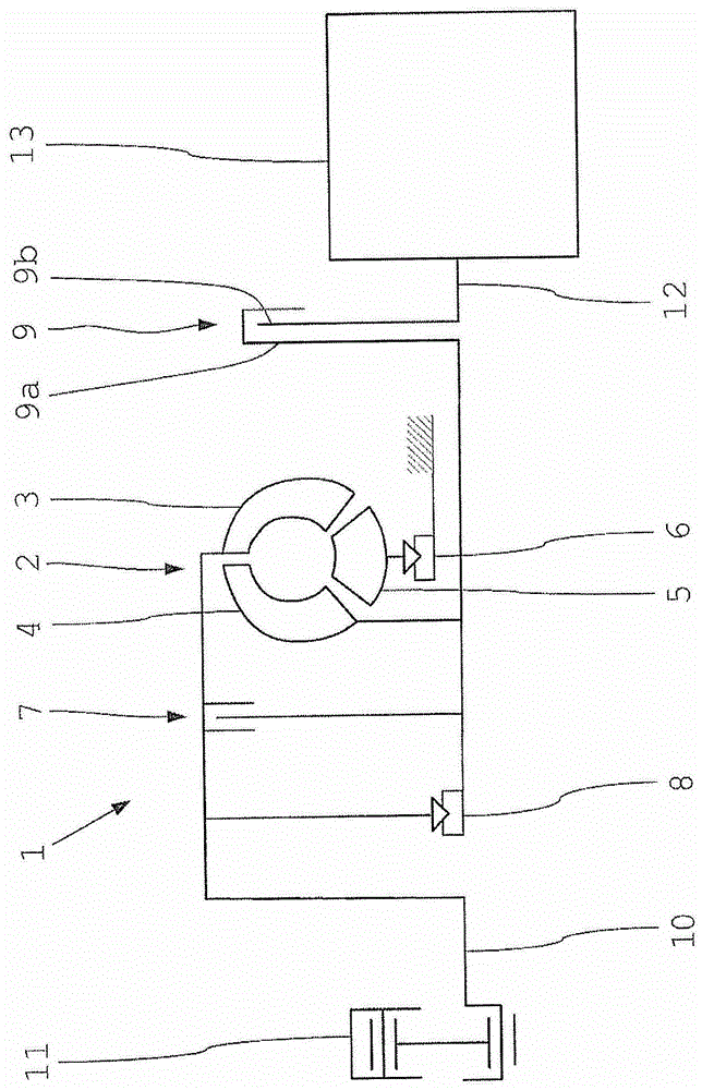
[0026] Such drivetrains for heavy-duty traction vehicles with a combination of a torque converter clutch and an automatic transmission are known per se. The torque converter clutch device 1 includes a hydraulic torque converter 2 , an automatically actuatable lock-up clutch 7 , a freewheel 8 and a shift clutch 9 . The lock-up clutch 7 and the shift clutch 9 are designed as friction clutches.

[0027] The torque converter 2 has a pump wheel 3 , a turbine wheel 4 and a guide wheel 5 in an oil-filled housing (not shown). The pump wheel 3 is connected to a drive shaft 10 or transmission shaft of a drive motor 11 designed as an internal combustion engine. The turbine wheel 4 is connected to the input side 9 a of the gearshift clutch 9 . The output side 9 b of the shift clutch 9 is connected to a transmission input shaft 12 of an automatic transmission 13 . The guide wheel 5 of the torque converter 2 is arranged between the pump wheel 3 and the turbine wheel 4 and is arranged mov...


PUM


Abstract

The present invention relates to a method for controlling a torque converter clutch device having a torque converter, a lock-up clutch and a shift clutch and in a power train of a motor vehicle, such as a heavy commercial vehicle, in the power flow Arranged between the transmission shaft of the drive motor and the transmission input shaft of the shift transmission, in this torque converter clutch device, the torque converter can be bridged between the transmission shaft and the shift clutch by means of the lock-up clutch, and the transmission input shaft disengagement of the torque converter and propshaft by means of a gearshift clutch, wherein the transmission input shaft is decoupled from the torque converter via the gearshift clutch when the transmission is shifted, and wherein the lock-up clutch is followed by a start-up process via the torque converter closure. In order to improve the driving comfort of vehicles equipped with the torque converter clutch and to reduce clutch wear, it is provided that the lock-up clutch is closed during the transmission shifting immediately following the start-up process with the shifting clutch open .

Description

technical field [0001] The invention relates to a method for controlling a torque converter clutch. Background technique [0002] Torque converter clutches are often used together with gearshift transmissions in commercial vehicles for demanding applications, such as the heavy-duty sector, the construction site sector or the military sector, in order to enable simple and low-wear adjustment of the vehicle even under the most difficult conditions. start possible. [0003] The known torque converter clutch device is arranged in the drive train of such a vehicle between the internal combustion engine and the gearshift transmission and comprises a hydrodynamic torque converter for converting the drive torque of the internal combustion engine; it is preferably designed as a lock-up of a friction clutch Clutch, the lock-up clutch is arranged parallel to the torque converter in the powertrain and can mechanically bridge the torque converter; usually also includes a coasting flywhe...

Claims


Application Information

Patent Timeline
Patent Type & Authority Patents(China)
IPC IPC(8): F16H61/14
CPCF16H61/143F16H61/68F16H2045/005F16H2061/146
Inventor 约翰内斯·克姆勒迈克·维特纳约阿希姆·施陶丁格安杰尔科·韦森亚克马库斯·毛雷尔
Owner ZF FRIEDRICHSHAFEN AG
Learn More