Fault recorder utilizing travelling wave fault location algorithm

A technology of fault recorder and traveling wave ranging, which is applied in the direction of the fault location, can solve the problems of unrecognizable reflected wave areas and identification problems of traveling wave method, and achieve the effect of improving the ranging accuracy

Inactive Publication Date: 2013-06-19
WUHAN ZHONGYUAN HUADIAN SCI & TECH +1
View PDF7 Cites 15 Cited by
  • Summary
  • Abstract
  • Description
  • Claims
  • Application Information

AI Technical Summary

Problems solved by technology

[0003] From the principle point of view, compared with the impedance method, traveling wave ranging is hardly affected by factors such as transition resistance and line asymmetry, and its accuracy is better than that of the impedance method; Identify the reflected wave area, and the near end is just the section where the impedance method is more accurate.

Method used


Image

  • Fault recorder utilizing travelling wave fault location algorithm

Examples


Embodiment 1

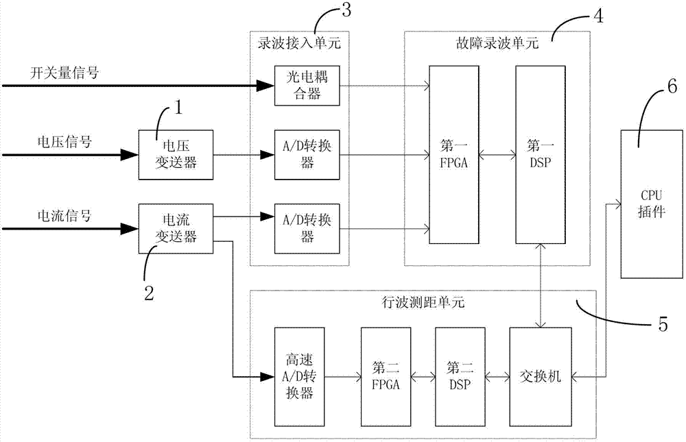
[0041] A fault recorder adopting a traveling wave ranging algorithm, comprising a voltage transmitter 1, a current transmitter 2, a recording access unit 3, a fault recording unit 4, a traveling wave ranging unit 5 and a CPU plug-in 6 ;

[0042] The voltage transmitter 1 is used to convert the voltage signal input in the power system into an analog voltage signal according to a linear ratio, and output the analog voltage signal to the wave recording access unit 3;

[0043] The current transmitter 2 is used to convert the current signal input in the power system into the same two analog current signals in a linear ratio, wherein one analog current signal is output to the wave recording access unit 3, and the other analog current signal is Output to traveling wave ranging unit 5;

[0044] The wave recording access unit 3 is used to receive the analog voltage signal sent by the voltage transmitter 1 and the analog current signal sent by the current transmitter 2, and receive the...


PUM


Abstract

The invention relates to fault recorder utilizing a travelling wave fault location algorithm. The fault recorder utilizing the travelling wave fault location algorithm comprises a voltage transmitter, a current transmitter, a wave recording access unit, a fault wave recording unit, a travelling wave fault location unit, and a central processing unit (CPU) plugin. The voltage transmitter can convert input voltage signals in an electric system into analogue voltage signals. The current transmitter converts input current signals in the electric system into two path analogue current signals. The wave recoding access unit converts the analogue voltage signals and the analogue current signals into digital voltage signals and digital current signals and the like. The fault wave recording unit samples the digital voltage signals and the digital current signals and the like. The travelling wave fault location unit converts the analogue current signals analog to digital (A / D) into high-speed digital current signals and the like. The CPU plugin receives traveling wave data and wave recording data and calculates a fault location according to the traveling wave data and wave recording. The fault recorder utilizing the travelling wave fault location algorithm can integrate fault recording and travelling wave fault location. Hardware investment of electric system high voltage transmission lines is reduced and time of repairing faults can be shortened.

Description

technical field [0001] The invention relates to a fault recorder of a power system, in particular to a fault recorder using a traveling wave ranging algorithm. Background technique [0002] At present, the fault recorders used in power systems all have traditional single-ended and double-ended ranging functions. The principle of this ranging is the impedance method, but the impedance method has accuracy problems, and their errors mainly come from The assumption of the algorithm itself is that the ranging accuracy is deeply affected by the transition resistance of the fault point. Only when the transition resistance of the fault point is zero can the distance of the fault point be calculated accurately. Moreover, due to the incomplete symmetry of the line in the actual system and the unknowable impedance value of the measurement end-to-side system, the ranging error is often much larger than the error standard given by some fault location products under ideal conditions. [...

Claims


Application Information

Patent Timeline
Patent Type & Authority Applications(China)
IPC IPC(8): G01R31/08
Inventor 段振坤卓露张雁忠陈奇任俊张小波李国武
Owner WUHAN ZHONGYUAN HUADIAN SCI & TECH
Why Eureka
Try Eureka