Converter valve control system inside direct current converter station

A DC converter station and control system technology, applied to electrical components, emergency power supply arrangements, circuit devices, etc., can solve problems such as abnormalities in the control system of converter valves, affecting maintenance efficiency, and disturbances in DC transmission systems, so as to ensure maintenance Effect

Inactive Publication Date: 2013-06-19
STATE GRID CORP OF CHINA +1
View PDF3 Cites 1 Cited by
  • Summary
  • Abstract
  • Description
  • Claims
  • Application Information

AI Technical Summary

Problems solved by technology

[0003] In the above power supply mode, a failure of any one of the power supply lines A and B or failure of any one of the four power conversion modules will cause a power supply board in the valve control panel to fail to work normally and cause the converter valve control system to malfunction. Abnormalities cause disturbances to the DC transmission system, and there are potential safety and stability risks; at the same time, when the existing system fails, it cannot be found in time whether it is the failure of the incoming power supply or the failure of the power conversion module, which affects the efficiency of maintenance

Method used


Image

  • Converter valve control system inside direct current converter station
  • Converter valve control system inside direct current converter station

Examples


Embodiment Construction

[0016] To facilitate the understanding of those skilled in the art, the present invention will be further described in detail below in conjunction with the accompanying drawings and specific embodiments.

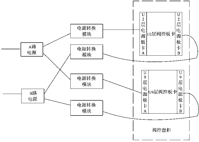
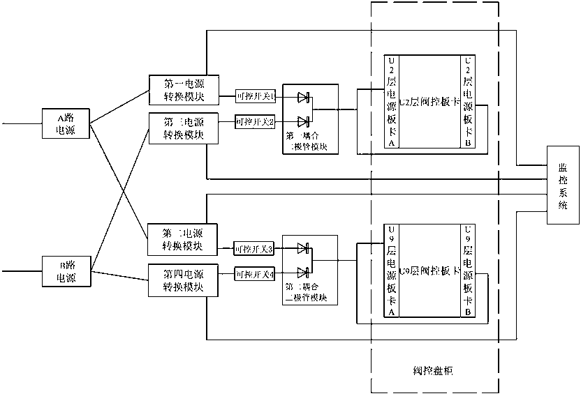
[0017] refer to figure 2 , a control system for a converter valve in a DC converter station, comprising: a power supply of A circuit, a first valve control board and a second valve control board of a B circuit power supply, first to fourth power conversion modules, first to fourth Controllable switch, first and second coupling diode modules.

[0018] In this embodiment, both the A-channel power supply and the B-channel power supply are 110V power supplies, the four power conversion modules are all 110 / 24V DC / DC power conversion modules of the same model and parameters, and the models of the coupling diode modules are all QUINT-DIODE / 40 , which is equivalent to two diodes, the input terminals of the two diodes are not connected, and the output terminals are connected in par...


PUM


Abstract

The invention relates to a converter valve control system inside a direct current converter station. An A route power source is connected with a first power source switching module and a second power source switching module, a B route power source is connected with a third power source switching module and a fourth power source switching module, the first power source switching module and the third power source switching module are respectively connected to an input end of a first coupling diode module through a first controllable switch and a second controllable switch, an output end of the first coupling diode module is connected to two power source board cards of a first valve control board card, and the second power source switching module and the forth power source switching module are respectively connected to two power source board cards of a second valve control board card. Each power source switching module is monitored by a monitoring system. When any rote of power source or any power source switching module has a fault, the converter valve control system can still transmit electricity to the outside safely and stably and the monitor system can emit warming to prompt the circuit or the power source switching module which has the fault so as to guarantee quickness and effectiveness of repair.

Description

technical field [0001] The invention relates to the field of power system control, in particular to a control system for a converter valve in a DC converter station. Background technique [0002] At present, the control panel cabinets of the converter valve control system of domestic DC converter stations are powered by dual-system single power supply. refer to figure 1 , the control panel includes U2 layer valve control board and U9 layer valve control board, U2 layer valve control board includes U2 layer power supply board A and U2 layer power supply board B, U9 layer valve control board includes U9 layer power supply Board A and U9 layer power board B, power board A and power board B are powered by the A power supply and the B power supply respectively, and the A power supply and the B power supply are respectively equipped with 2 power conversion modules, and the final output is independent The four-way power supply separately supplies power to the four power supply bo...

Claims


Application Information

Patent Timeline
IPC IPC(8): H02J9/04
Inventor 蒋久松
Owner STATE GRID CORP OF CHINA
Why Eureka
Try Eureka