
Device for preventing current of buck circuit from flowing reversely, converter and power supply

A circuit current and voltage comparison circuit technology, applied in the direction of output power conversion device, DC power input conversion to DC power output, adjustment of electrical variables, etc., can solve the problem of low impedance drop at the input end, current backfeeding, and pre-bias at the output setting voltage etc.

Active Publication Date: 2013-06-19
HUAWEI TECH CO LTD
View PDF6 Cites 40 Cited by
  • Summary
  • Abstract
  • Description
  • Claims
  • Application Information

AI Technical Summary

Problems solved by technology

The backfeed problem is particularly serious in the following two cases: the first case is that the input end has a low impedance drop, and the second case is that there is a pre-biased voltage at the output when the power supply is turned on
[0003] In the second case, the power supply with bus power supply is especially serious, because the total capacitance on the load side of the bus is larger, and the problem of current backfeeding is more prone to occur
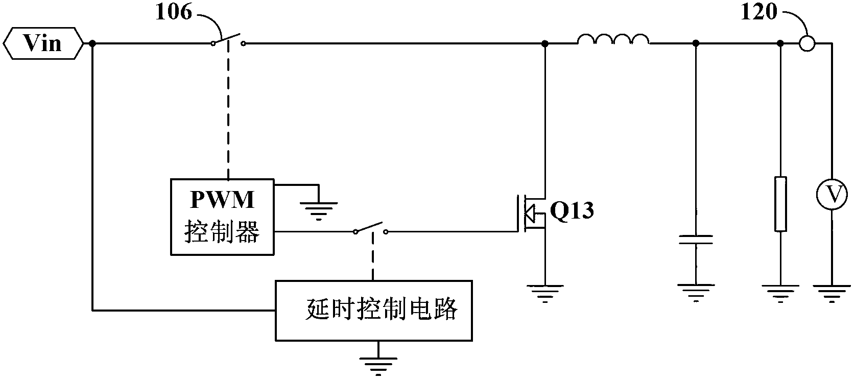
However, since the pre-bias voltage of the actual voltage output terminal of the buck circuit is actually uncertain, the delay control time required is short when it is large; on the contrary, it is large when it is small, so the existing fixed delay Sometimes it's hard to see everything
For example, when the pre-bias voltage is high, it is still delayed for a long time to control the freewheeling switch Q13 to enter the normal switching state, and the output filter inductor will change from discontinuous operation (DCM) to continuous current mode (Continuous Current Mode, CCM) sudden switching caused by the output voltage power-down phenomenon

Method used


Image

  • Device for preventing current of buck circuit from flowing reversely, converter and power supply
  • Device for preventing current of buck circuit from flowing reversely, converter and power supply
  • Device for preventing current of buck circuit from flowing reversely, converter and power supply

Examples


Embodiment Construction

[0033] In order to make the object, technical solution and advantages of the present invention clearer, the present invention will be further described in detail below in conjunction with the accompanying drawings. Obviously, the described embodiments are only some embodiments of the present invention, rather than all embodiments . Based on the embodiments of the present invention, all other embodiments obtained by persons of ordinary skill in the art without making creative efforts belong to the protection scope of the present invention.

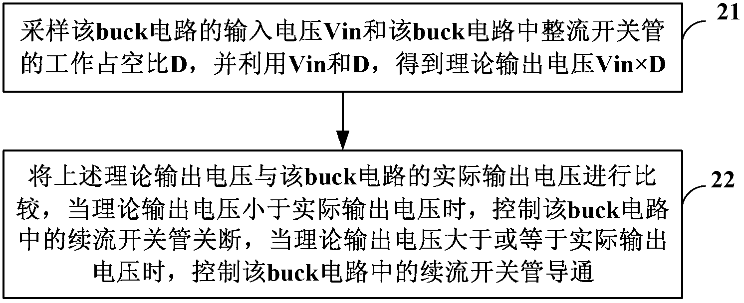
[0034] figure 2 It is a flowchart of a method for preventing current reversal of a step-down buck circuit provided by an embodiment of the present invention. Such as figure 2 As shown in , assuming that the output terminal of a buck circuit has a pre-bias voltage, the methods to prevent the reverse current of the buck circuit include:

[0035] Step 21: Sampling the input voltage Vin of the buck circuit and the duty ratio D of the recti...


PUM


Abstract

The invention provides a device for preventing current of a buck circuit from flowing reversely, a convertor and a power supply. The method comprises the following steps of: sampling input voltage Vin of the buck circuit and a work duty ratio D of a rectification switching tube in the buck circuit, and obtaining theoretical output voltage Vin*D by using the Vin and D; comparing the theoretical output voltage and actual output voltage of the buck circuit; when the theoretical output voltage is less than the actual output voltage, controlling a follow current switching tube in the buck circuit to be turned off; and when the theoretical output voltage is more than or equal to the actual output voltage, controlling the follow current switching tube in the buck circuit to be turned on. The turn-on and turn-off condition of the follow current switching tube of the buck circuit is actually controlled, and reverse current in an output filter inductor is avoided under the condition that an output end has pre-bias when the follow current switching tube is turned on in a normal turn-on and turn-off state.

Description

technical field [0001] The invention relates to power supply technology, in particular to a device, converter and power supply for preventing the reverse current of a step-down buck circuit. Background technique [0002] Compared with diode rectification, synchronous rectification has the characteristic of bidirectional current flow, so such topological structures are all bidirectional topologies. In the non-isolated topology step-down (buck) circuit, replacing the flywheel diode with a synchronous switch is also a bidirectional topology. In this structure, energy can flow from the power input to the output, and from the output to the input. Among them, energy flows from the output to the input, which is the so-called current backfeeding problem. The backfeed problem is particularly serious in the following two situations: the first situation is that the input end has a low impedance drop, and the second situation is that there is a pre-biased voltage at the output when the...

Claims


Application Information

Patent Timeline
IPC IPC(8): H02M1/32H02M3/155
Inventor 樊晓东
Owner HUAWEI TECH CO LTD
Learn More