
E1 signal sending device and receiving device

A technology of a signal sending device and a signal receiving device, which is applied in the field of network equipment in the field of communication technology, can solve the problems of complicated production and on-site installation, E1 transmission line error code, and increased cost, so as to reduce production and installation costs and avoid errors. code or broken link, to ensure the effect of signal transmission

Inactive Publication Date: 2014-12-03
JIANGSU JINDING BOILER
View PDF4 Cites 0 Cited by
  • Summary
  • Abstract
  • Description
  • Claims
  • Application Information

AI Technical Summary

Problems solved by technology

Because the hardware design of the single board cannot be unified, the production and on-site installation are complicated, and two sets of codes are required for production and management, which increases the cost; if the cable matching the single board is used incorrectly, for example, a 75-ohm impedance The matching of twisted-pair cables with ohmic impedance will lead to abnormal signal transmission, and E1 transmission lines will have bit errors or link breaks

Method used


Image

  • E1 signal sending device and receiving device
  • E1 signal sending device and receiving device
  • E1 signal sending device and receiving device

Examples


Embodiment Construction

[0031] Specific embodiments of the present invention will be described below in conjunction with the accompanying drawings.

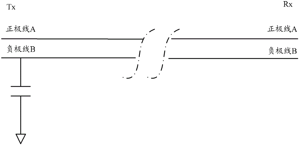
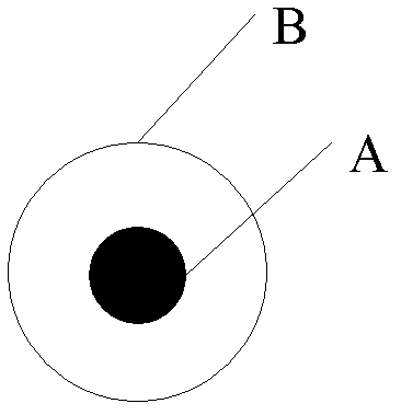
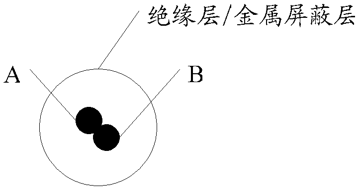
[0032] In the embodiment of the present invention, in order to avoid interference from the E1 signal transmission line, one way is to adopt a unified processing method for the E1 signal transmission line (a coaxial cable with an impedance of 75 ohms or a twisted pair cable with an impedance of 120 ohms). The negative line at the sending end of the signal transmission line is grounded through a capacitor. Another way is to ground the negative wires of the sending end and the receiving end of the E1 signal transmission line through a capacitor. In the E1 signal sending device and / or the E1 signal receiving device, connect the negative line of the E1 signal transmission line to the ground terminal of the board, or the ground terminal of the rack, or the ground terminal of the subrack through a capacitor to realize the negative pole. wire to ground.

[00...


PUM


Abstract

Provided in an embodiment of the present invention are an E1 signal transmission line, an E1 signal sending device and a receiving device. The E1 signal transmission line comprises a sending terminal and a receiving terminal; the sending terminal and the receiving terminal respectively comprise a positive wire and a negative wire; and the negative wire of the sending terminal of the E1 signal transmission line is grounded through a capacitor. In the present invention, grounding the central tap of the transformer in the E1 signal transmission line, or the E1 signal sending device, or the E1 signal receiving device can achieve the objective of anti-interference. The grounding treatment mode in the present invention neither distinguishes a 75 ohmic resistance of coaxial cable from a 120 ohmic resistance of twisted-pair cable, nor distinguishes a 75-ohm of veneer from a 120-ohm of veneer. Therefore, the design of the veneers can be unified, the cost for manufacturing and installation is reduced, the normal transmission of signals is ensured, and error code or link disconnection is avoided.

Description

technical field [0001] The invention relates to network equipment in the technical field of communication, in particular to an E1 signal transmission line, an E1 signal sending device and a receiving device. Background technique [0002] E1 signal is a communication signal transmission method recommended by ITU-T, which is widely used in data communication equipment. The electrical interface of the E1 signal conforms to the suggestion of ITU-T G.703 (2001, 11) "Physical / electrical characteristics of hierarchical digital interfaces", and the frame structure conforms to the suggestion of ITU-T G.704. The rate of E1 signal transmission is 2048kbit / s, and the physical connection includes a pair of receiving lines (receiving end) and a pair of sending lines (sending end). There are two line impedance matching methods for E1 signal, one is 75 ohm impedance, using coaxial cable for signal transmission; the other is 120 ohm impedance, using symmetrical twisted pair cable for signal...

Claims


Application Information

Patent Timeline
Patent Type & Authority Patents(China)
IPC IPC(8): H04B3/50
CPCH03H1/00H04M19/001H03H1/0007
Inventor 俞恢春王庆海
Owner JIANGSU JINDING BOILER
Learn More