
Self-locking structure for plastic mold cylinder slide block

A technology of plastic mold and self-locking structure, applied in the field of self-locking structure, can solve the problems of high cost, unqualified molded products, easy leakage, etc., and achieve the effects of low manufacturing cost, higher defective rate and low defective rate.

Active Publication Date: 2013-06-26
宁海县现代模具有限公司
View PDF4 Cites 6 Cited by
  • Summary
  • Abstract
  • Description
  • Claims
  • Application Information

AI Technical Summary

Problems solved by technology

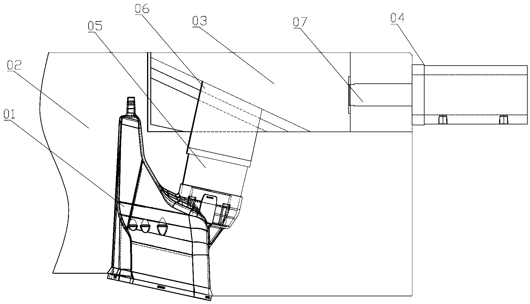
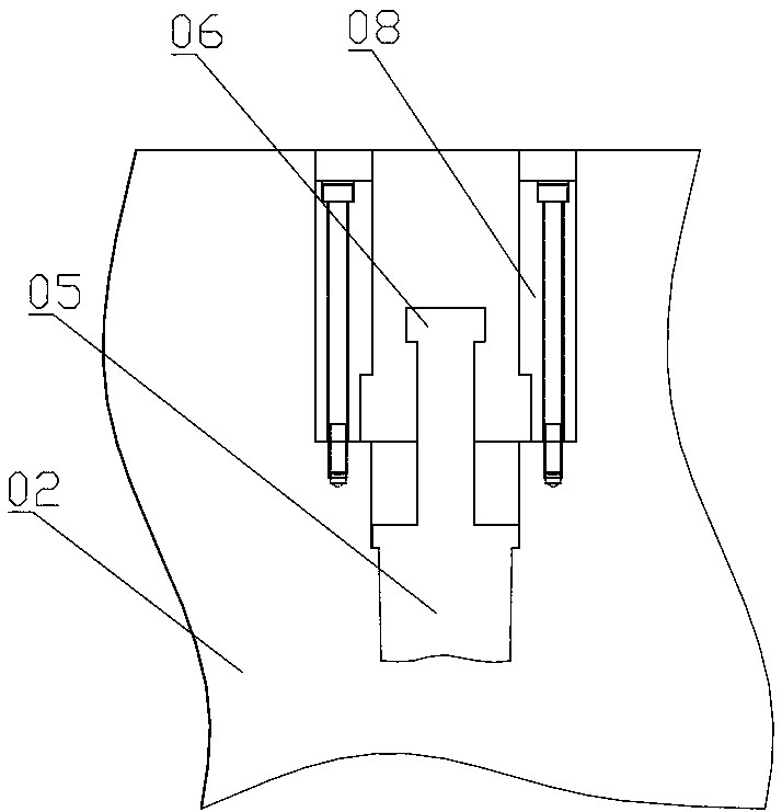
The above-mentioned oil cylinder slider core-pulling structure has the following disadvantages in actual work: because there is no blocking part between the slider 03 and the piston rod 07 of the oil cylinder 04, when the mold is in the injection molding process, a Larger pressure, this pressure will be transmitted from the core body 05 to the slider 03, if the pressure is greater than the thrust applied by the cylinder 04 to the piston rod 07, then the slider 03 will move to the side of the cylinder 04, so that through the feather key 06 Drive the core-pulling body 05 out of the product cavity 01 for a certain distance, obviously this will affect the molding of the product where the core-pulling body 05 is in contact with the product cavity 01; thus resulting in unqualified molded products
The former of the two schemes has potential safety hazards, and leakage is likely to occur when the pressure in the oil cylinder 04 is too high
The latter is complicated in structure, high in cost, and the stability of electric control is not high due to the influence of electric power.

Method used


Image

  • Self-locking structure for plastic mold cylinder slide block
  • Self-locking structure for plastic mold cylinder slide block
  • Self-locking structure for plastic mold cylinder slide block

Examples


Embodiment Construction

[0019] The present invention will be described in further detail below in conjunction with the accompanying drawings.

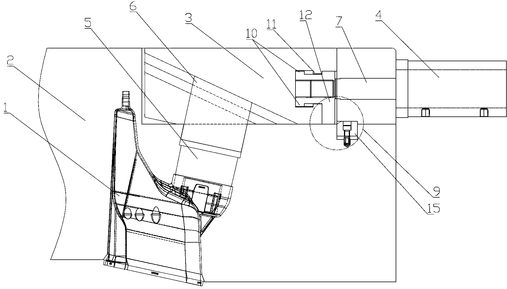
[0020] combined with image 3 to attach Figure 7 , a self-locking structure of a plastic mold oil cylinder slider, which includes a fixed mold 2, a first slider 3, an oil cylinder 4 and a core-pulling body 5, and the first slider 3 is slidably connected with the core-pulling body 5 and the fixed mold 2 respectively ; A block 15 is provided between the first slide block 3 and the oil cylinder 4, the block 15 is embedded in the fixed mold 2, and an elastic part that can push the top of the block 15 out of the fixed mold 2 is installed below the block 15; The slider 3 is provided with a briquetting part for pressing back the upper part of the stopper 15 in the fixed mold 2, one end of the briquetting part is fixedly connected with the piston rod 7 of the oil cylinder 4; the other end of the briquetting part is connected with the first slider 3 Sliding connect...


PUM


Abstract

The invention provides a self-locking structure for a plastic mold cylinder slide block. The self-locking structure is simple, low in manufacturing cost, safe and reliable. The self-locking structure comprises a fixed die (2), a first slide block (3), a cylinder (4) and a core-pulling body (5), wherein the first slide block (3) is in sliding connection with the core-pulling body (5) and the fixed die (2) respectively. The self-locking structure is characterized in that a stopper (15) is arranged between the first slide block (3) and the cylinder (4) and is embedded in the fixed die (2); an elastic part which can eject the upper part of the stopper (15) out of the fixed die (2) is arranged below the stopper (15); a block pressing part for pressing the upper part of the stopper (15) back to the fixed die (2) is arranged on the first slide block (3); one end of the block pressing part is fixedly connected with a piston rod (7) of the cylinder (4), and the other end of the block pressing part is in sliding connection with the first slide block (3); a limiting part for preventing the block pressing part from sliding out of one end close to the cylinder (4) is arranged on the first slide block (3); and when the block pressing part slides to the limiting part, the first slide block (3) can be driven to slide in the fixed die (2).

Description

technical field [0001] The invention relates to a self-locking structure of a plastic mold oil cylinder slider. Background technique [0002] Plastic molds are widely used in industrial production to manufacture various plastic products. In actual use, according to the structure of the product, it is often necessary to design a core-pulling body on the mold, and the most commonly used method for pulling the core-pulling body is the pump composed of the cylinder slider. core structure. further combined with figure 1 And attached figure 2 , the core-pulling structure composed of the plastic mold oil cylinder slider includes a slider 03, an oil cylinder 04 and a core-pulling body 05, the slider 03 is connected to the core-pulling body 05 through an oblique sliding key 06, and the sliding key 06 It is a T-shaped sliding key; the core-pulling body 05 can slide in the slider 03, and the end of the core-pulling body 05 is connected with the product cavity 01; the oil cylinder 0...

Claims


Application Information

Patent Timeline
Patent Type & Authority Applications(China)
IPC IPC(8): B29C45/33
Inventor 葛文枝
Owner 宁海县现代模具有限公司
Learn More