Belt Type Continuously Variable Transmission For Vehicle

A technology for continuously variable transmissions and vehicles, which is applied to components with teeth, belts/chains/gears, transmissions, etc., which can solve the problems of increased manufacturing costs and weight of continuously variable transmissions, and achieve simple structures and suppress fixed wheels dumping effect

Inactive Publication Date: 2012-12-05
TOYOTA JIDOSHA KK
View PDF13 Cites 3 Cited by
  • Summary
  • Abstract
  • Description
  • Claims
  • Application Information

AI Technical Summary

Problems solved by technology

To solve this problem, for example, increase the thickness of the fixed wheel in the axial direction to improve the strength, but this has the disadvantages of increasing the manufacturing cost and weight of the continuously variable transmission.

Method used


Image

  • Belt Type Continuously Variable Transmission For Vehicle
  • Belt Type Continuously Variable Transmission For Vehicle
  • Belt Type Continuously Variable Transmission For Vehicle

Examples


Embodiment 1

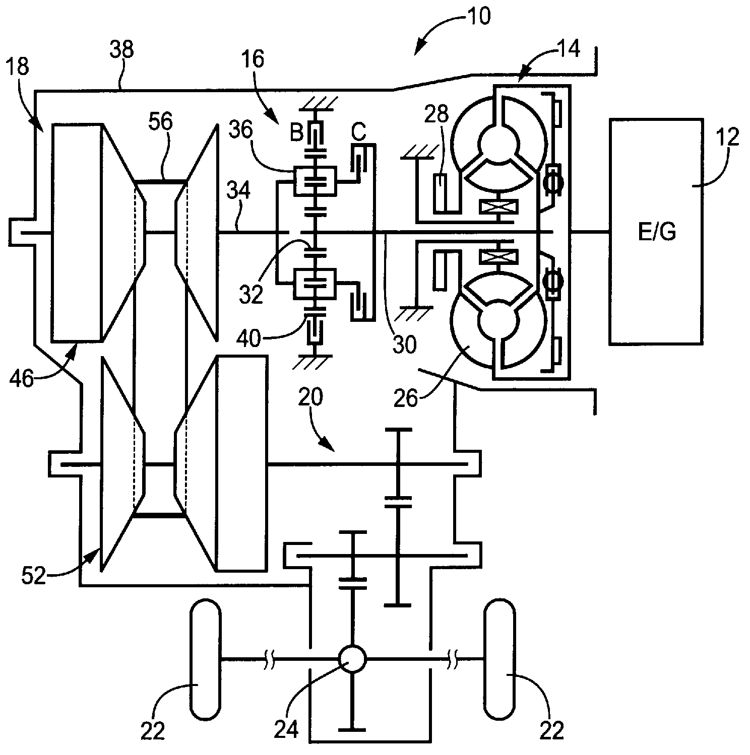
[0045] figure 1 It is a skeleton diagram of a vehicle power transmission device 10 to which the present invention is preferably applied. figure 1 Here, the vehicle power transmission device 10 is a power transmission device for an FF (Front Engine Front Wheel Drive) vehicle, and is connected to an engine 12 known as a vehicle drive source. This vehicle power transmission device 10 includes: a fluid torque converter 14 known as a fluid transmission device that transmits the torque of the engine 12 through a fluid; A forward and reverse switching device 16 for switching the rotational direction of the torque transmitted from the torque converter 14 between reverse directions; a vehicle that converts the torque transmitted through the forward and reverse switching device 16 into a torque corresponding to the load A belt-type continuously variable transmission (hereinafter referred to as continuously variable transmission) 18; a reduction gear device 20 connected to the output si...

Embodiment 2

[0065] Next, other embodiments of the present invention will be described. In addition, in the description of the following examples, the parts that overlap with each other in the examples are given the same reference numerals, and the description thereof will be omitted.

[0066] Figure 4 It is an enlarged cross-sectional view showing a secondary pulley 202 and a parking gear 204 in a continuously variable transmission 200 according to another embodiment of the present invention. Such as Figure 4As shown, the fixed pulley 206 of the secondary pulley 202 has an annular fitting portion 206 a projecting toward the parking gear 204 from the outer peripheral portion of the rear surface 208 on the opposite side to the movable pulley 66 . Furthermore, the parking gear 204 includes: an annular plate-shaped main body portion 204a fixedly provided on the outer peripheral surface of the output shaft 50; The annular protrusion 204b engages in the radial direction within the engageme...

Embodiment 3

[0072] Figure 5 It is an enlarged cross-sectional view showing a secondary pulley 302 and a parking gear 304 in a continuously variable transmission 300 according to another embodiment of the present invention. Such as Figure 5 As shown, in the fixed sheave 306 of the secondary pulley 302 , a stepped end surface 310 is formed on the inner peripheral portion of the back surface 308 opposite to the movable sheave 66 . Furthermore, the parking gear 304 includes: a main body 304a and an annular protrusion 304b similar to the main body 86a and the annular protrusion 86b of the parking gear 86 of Embodiment 1; and an annular protrusion from the main body 304a. A stopper portion 304c protrudes from the inner peripheral side of the portion 304b toward the stepped end surface 310 of the rear surface 308 . The stopper portion 304c abuts against the stepped end surface 310 of the rear surface 308 when the pressing force exerted on the fixed wheel 306 from the annular protrusion 304b ...


PUM


Abstract

Provided is a belt type continuously variable transmission for a vehicle such that the bending-over of a fixed sheave can be restricted. A parking gear (86) comprising a disk-shaped main body section (86a) and an annular protrusion (86b) is provided on that side of the fixed sheave (64) which is other than the side facing a movable sheave (66), said disk-shaped main body section (86a) being fixed to an output shaft (50), for example, by being splined together therewith, and said annular protrusion (86b) protruding from the main body section (86a) toward that wall surface of the fixed sheave (64) which is other than the side facing the movable sheave (66), that is, toward a back surface (90), and abutting the back surface (90) at that radial position which corresponds to the maximum engagement radius of a transmission belt (56). Therefore, even if the fixed sheave (64) is subjected to an axial reaction force (Fc2) in an axial direction (C2) by the transmission belt (56), that area of the back surface (90) of the fixed sheave (64) which is outward of the minimum engagement radius of the transmission belt (56) is supported by the parking gear (86), which is formed by adding only relatively simple changes to a conventional one. Consequently, the bending-over of the fixed sheave (64) can be restricted.

Description

technical field [0001] The present invention relates to a belt-type continuously variable transmission for a vehicle, and more particularly to a technique for suppressing the tilting of a fixed wheel. Background technique [0002] There is known a belt-type continuously variable transmission for vehicles, which includes: an input shaft and an output shaft arranged parallel to each other; a pair of variable groove width pulleys provided on the outer peripheral sides of the input shaft and the output shaft; In the belt in the V-groove of the pair of variable-groove-width pulleys, the belt-type continuously variable transmission for vehicles changes the winding diameter of the belt by changing the groove width of the V-groove, thereby changing the speed. Varies steplessly. For example, Patent Documents 1 to 9 describe the belt-type continuously variable transmission for vehicles. [0003] Patent Document 1: Japanese Patent Laid-Open No. 2008-309232 [0004] Patent Document 2...

Claims


Application Information

Patent Timeline
Patent Type & Authority Applications(China)
IPC IPC(8): F16H9/18F16H63/34
CPCF16H63/3425F16H9/18
Inventor 门川正德
Owner TOYOTA JIDOSHA KK
Why Eureka
Try Eureka