Rail transit train rear-end prevention device based on pseudo-random code radio frequency distance measurement

A rail transit train and radio frequency ranging technology, which is applied in the field of rail transit, can solve the problems of difficult communication distance between wireless coding transmitter/receiver, large fluctuations in the distance between vehicles for preventing rear-end collisions, and large fluctuations in the longest distance of wireless communication. Improve driving safety and prevent rear-end collisions

Inactive Publication Date: 2013-06-26
TONGJI UNIV
View PDF6 Cites 12 Cited by
  • Summary
  • Abstract
  • Description
  • Claims
  • Application Information

AI Technical Summary

Problems solved by technology

Because radio frequency signal transmission is affected by channel fading and multipath, there is randomness in the received signal strength, so the farthest distance of wireless communication fluctuates greatly, resulting in large fluctuations in the distance between vehicles to prevent rear-end collisions, and there is uncertainty
In the field of urban rail transit, the braking distance of trains does not exceed 200 meters, so the distance between trains to prevent rear-end collisions is relatively short, only 200 to 300 meters. At this distance level, the communication distance of wireless coding transmitter / receiver is more difficult to be accurate. define

Method used


Image

  • Rail transit train rear-end prevention device based on pseudo-random code radio frequency distance measurement
  • Rail transit train rear-end prevention device based on pseudo-random code radio frequency distance measurement
  • Rail transit train rear-end prevention device based on pseudo-random code radio frequency distance measurement

Examples


Embodiment Construction

[0022] The present invention will be further described below in conjunction with the embodiments shown in the accompanying drawings.

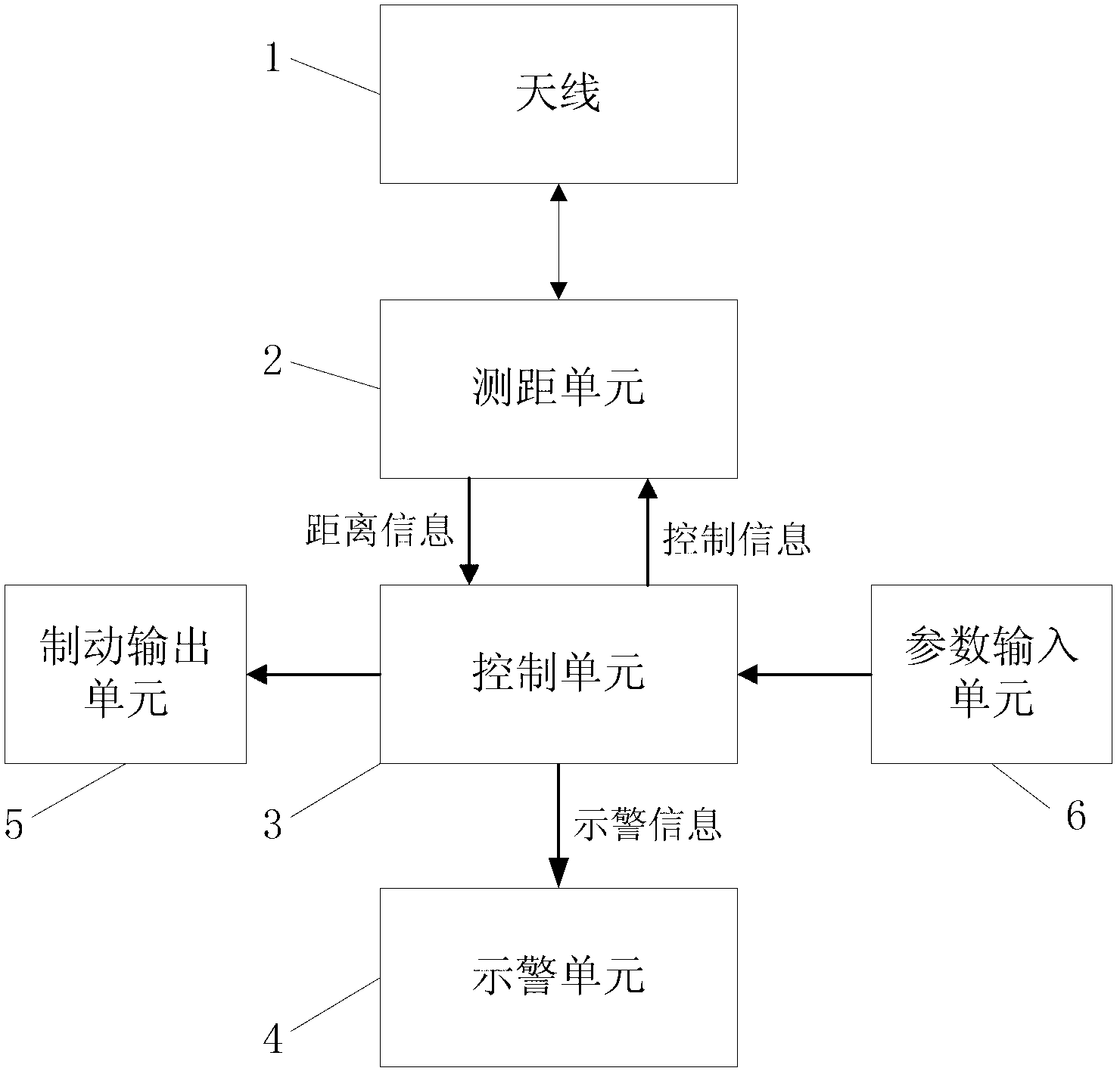
[0023] Depend on figure 1 It can be seen that the anti-rear collision device described in the present invention includes: antenna 1 , distance measuring unit 2 , control unit 3 , warning unit 4 , brake output unit 5 and parameter input unit 6 . Wherein, the antenna 1 is connected to the distance measuring unit 2 , the distance measuring unit 2 is connected to the control unit 3 , and the control unit 3 is connected to the warning unit 4 , the brake output unit 5 and the parameter input unit 6 respectively.

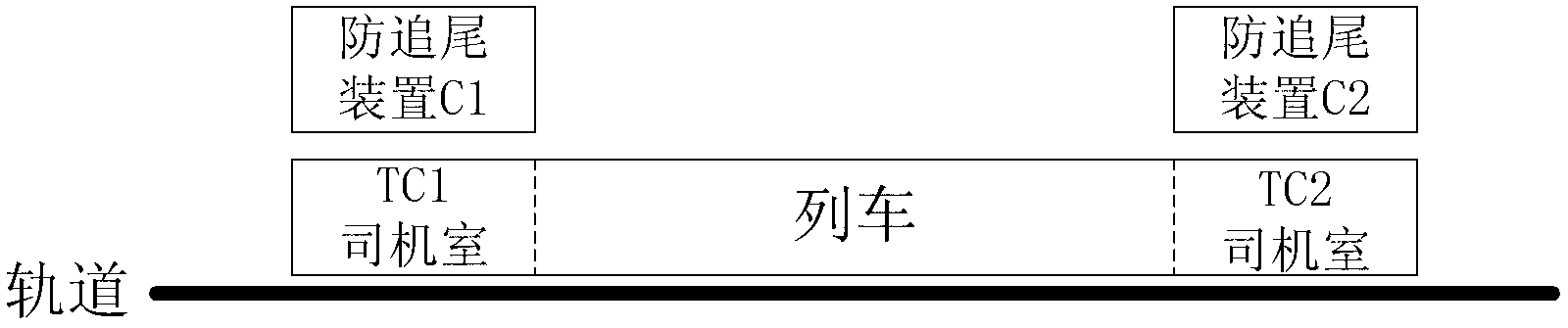
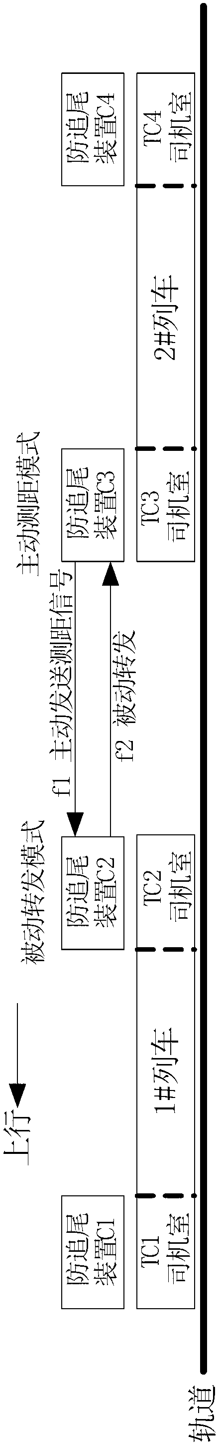
[0024] figure 2 The method for installing and configuring the device of the present invention on a train is shown. A single set of the device completes the anti-rear-end collision function of rail transit trains in one running direction. Usually, there are 2 directions of train running, namely uplink and downlink. The specific definiti...


PUM


Abstract

The invention provides a rail transit train rear-end prevention device based on pseudo-random code radio frequency distance measurement and belongs to the technical field of rail transit. The device comprises an antenna, a distance measurement unit, a control unit, a warning unit and a parameter input unit. The distance measurement unit is connected with the antenna, the control unit is connected with the distance measurement unit, and the warning unit and the parameter input unit are respectively connected with the control unit. The distance measurement unit is used for measuring the distance between a front train and a back train in the same traveling direction with the method of pseudo-random code radio frequency distance measurement. The parameter input unit acquires information of traveling direction where the train is located and transmits the information to the control unit. The control unit sets a working mode and radio frequency points of the distance measurement unit, compares the distance between the front train and the back train to judge whether the trains are safe and sends an action command to the warning unit. The warning unit displays the distance or gives out warning. The rail transit train rear-end prevention device based on the pseudo-random code radio frequency distance measurement can acquire accurate and real-time distance data of the front train and the back train without support of other devices, output warning information or braking commands, monitor the distance between the front train and the back train effectively, prevent rear-end accidents and improve traffic safety.

Description

technical field [0001] The invention belongs to the technical field of rail transit, and relates to a rear-end collision prevention device for rail transit trains. Background technique [0002] During the operation of the rail transit train, the front and rear trains must maintain a sufficient distance, which is usually required to be greater than the braking distance of the train, so as to ensure the safety of the train. The rail transit operation control system is the technical guarantee for train operation safety. It is used to ensure the safe interval between front and rear trains and prevent dangerous events such as train rear-end collisions. This system is a complex automation system. When the rail transit operation control system breaks down and is out of use, the driver is often required to drive or watch manually to ensure driving safety. When a train passes through curves or up and down slopes, limited by terrain conditions, the lookout distance is short, and it m...

Claims


Application Information

Patent Timeline
Patent Type & Authority Applications(China)
IPC IPC(8): B61L23/00B61L23/34
Inventor 沈拓欧冬秀韦乐香袁志鹏
Owner TONGJI UNIV
Why Eureka
Try Eureka