Light guide plate and backlight unit with same

A technology of backlight module and light guide plate, which is applied in the field of backlight module and can solve the problem of small light output range

Active Publication Date: 2013-06-26
江门市五洲有机玻璃有限公司
View PDF4 Cites 8 Cited by
  • Summary
  • Abstract
  • Description
  • Claims
  • Application Information

AI Technical Summary

Problems solved by technology

However, after the light is reflected by the above-mentioned V-shaped microstructure, the range of light emitting from the front side of the light guide plate is relatively small.

Method used


Image

  • Light guide plate and backlight unit with same
  • Light guide plate and backlight unit with same
  • Light guide plate and backlight unit with same

Examples


Embodiment Construction

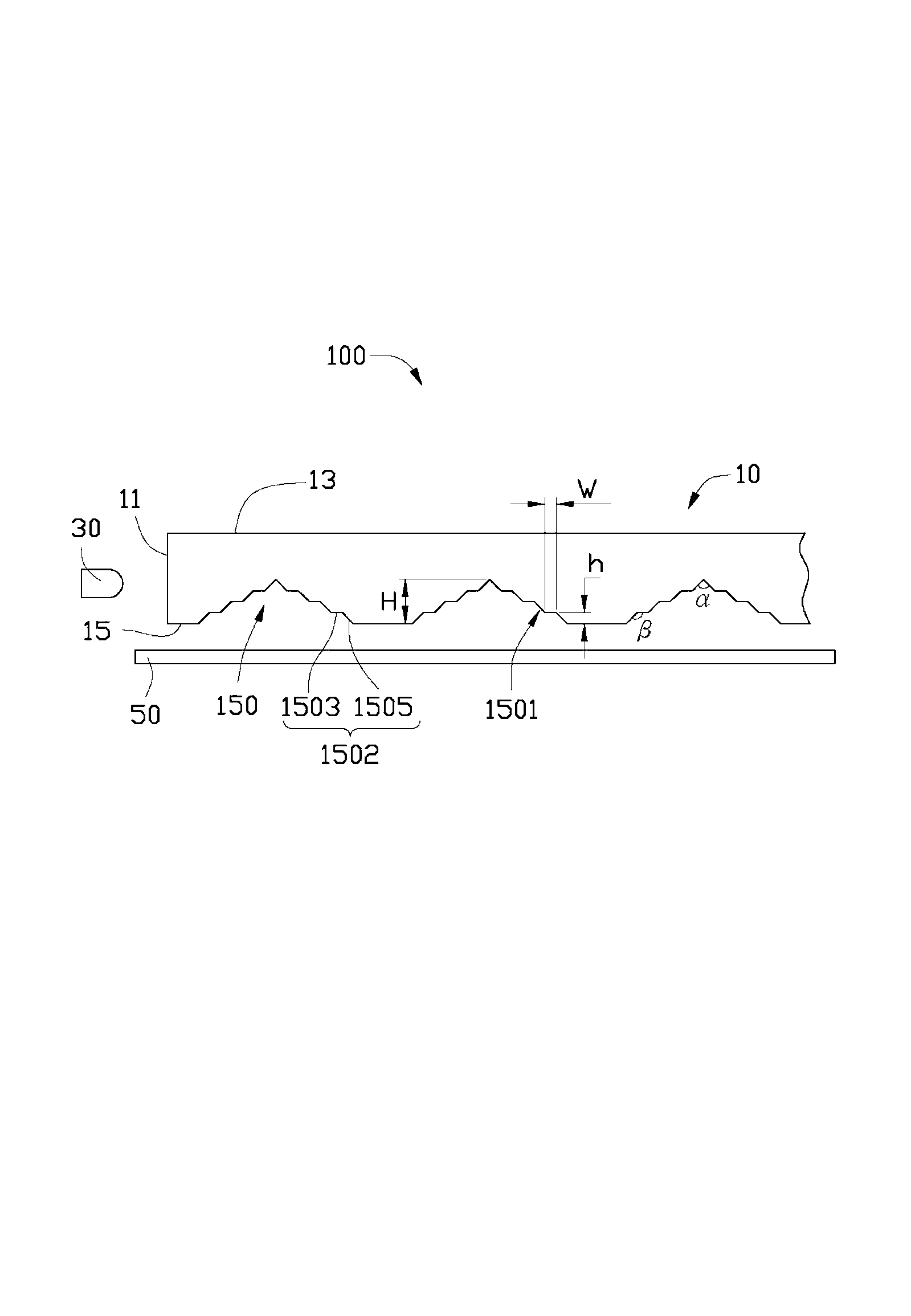
[0015] see figure 1 , the backlight module 100 according to Embodiment 1 of the present invention includes a light guide plate 10 , a light source 30 and a reflector 50 .

[0016] The light guide plate 10 is substantially in the shape of a rectangular plate, and has an incident surface 11 , an outgoing surface 13 , and a reflective surface 15 opposite to the outgoing surface 13 . The incident surface 11 connects the outgoing surface 13 and the reflective surface 15 , light enters the light guide plate 10 from the incident surface 11 , is reflected by the reflective surface 15 , and exits from the outgoing surface 13 . A plurality of parallel microstructures 150 recessed toward the inside of the light guide plate 10 are formed on the reflective surface 15 . The microstructure 150 is an elongated groove with a substantially inverted V-shaped cross section. The microstructure 150 is formed with two substantially symmetrical sidewalls 1501 , each sidewall 1501 includes a plurali...


PUM

PropertyMeasurementUnit
Top angleaaaaaaaaaa

Abstract

A light guide plate comprises an incident surface, an emergent surface and a reflection surface which is arranged opposite to the emergent surface. The incident surface is connected with the emergent surface and the reflection surface, and a plurality of micro structures which are arranged inside the light guide plate in a recessed mode are formed on the reflection surface. Every micro structure is a stripe groove with a cross section of a reversed V shape and provided with two opposite sidewalls, and each sidewall comprises a plurality of stepped parts which are sequentially connected. The sidewalls of the micro structures formed on the light guide plate are in the stepped shape, so that the step-shaped micro structures can collect light and further enable the emergent range of emergent light to be larger when compared with common sidewalls which have a plane V-shaped structure. The invention also provides a backlight unit with the light guide plate.

Description

technical field [0001] The invention relates to a light guide plate and a backlight module using the same. Background technique [0002] The light guide plate is an important component in the backlight module. It is used to guide the light emitted by the point light source or the line light source to emit from the plane. It has a light incident surface, a reflective surface, an outgoing surface and multiple sides. Microstructures are usually provided on the reflective surface of the light guide plate to improve light utilization efficiency and light uniformity, such as V-shaped microstructures. However, after the light is reflected by the above-mentioned V-shaped microstructure, the range of emitting light from the front side of the light guide plate is relatively small. Contents of the invention [0003] In view of the above situation, it is necessary to provide a light guide plate capable of increasing the emission range of light; [0004] In addition, it is also neces...

Claims


Application Information

Patent Timeline
IPC IPC(8): G02B6/00G02B5/04F21S8/00F21V8/00
Inventor 王何立颖
Owner 江门市五洲有机玻璃有限公司
Why Eureka
Try Eureka