Display drive circuit and drive method thereof as well as display device

A display driver and circuit technology, applied in static indicators, static memories, instruments, etc., can solve the problem of not being able to shield the first output enable signal, etc.

Active Publication Date: 2013-06-26
BOE TECH GRP CO LTD +1
View PDF5 Cites 8 Cited by
  • Summary
  • Abstract
  • Description
  • Claims
  • Application Information

AI Technical Summary

Problems solved by technology

[0005] The present invention provides a display driving circuit, its driving method, and a display device, which are used to solve the problem in the prior art that the first output enabling signal cannot be shielded according to the shielding signal, and then the data that may cause abnormal display is eliminated.

Method used


Image

  • Display drive circuit and drive method thereof as well as display device
  • Display drive circuit and drive method thereof as well as display device
  • Display drive circuit and drive method thereof as well as display device

Examples


Embodiment 1

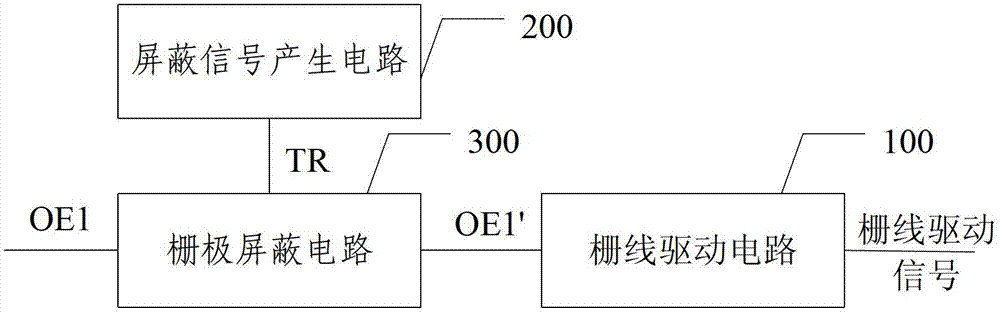
[0031] image 3 It is the circuit diagram of the display drive circuit described in the embodiment of the present invention, such as image 3 As shown, a display driving circuit provided by an embodiment of the present invention includes:

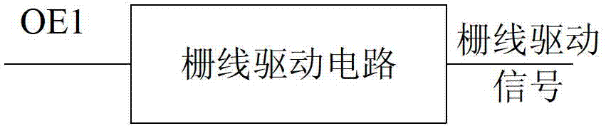
[0032] The gate line driving circuit 100 is used to separate the gate line driving signals of adjacent rows according to the first output enable signal OE1;

[0033] Also includes:

[0034] The shielding signal generation circuit 200 triggers and generates a shielding signal TR when the gate drive signal needs to be turned off;

[0035] The gate line shielding circuit 300, the first input terminal of the gate line shielding circuit 300 inputs the first output enable signal OE1, the second input terminal inputs the shielding signal TR, and the output terminal is connected to the gate line driving circuit 100, so The gate line shielding circuit 300 is used for shielding the first output enable signal OE1 according to the mask signal TR, so...

Embodiment 2

[0051] The present invention also provides a display device, including the display driving circuit described in the present invention.

[0052] By using the display drive circuit of the present invention on the display device, the first output enable signal and the gate line drive circuit can be used to shield the gate line drive signal, thereby controlling the corresponding gate line, and removing data that may cause abnormal display, The display driving circuit has a simple structure and is easy to install on the display device.

Embodiment 3

[0054] Figure 5 is a flow chart of the driving method described in the embodiment of the present invention, such as Figure 5 As shown, Embodiment 3 of the present invention provides a driving method for driving the display driving circuit as described in Embodiment 1 of the present invention, which separates the gate line driving signals of adjacent rows according to the first output enable signal, and further includes:

[0055] Step S101, when the gate driving signal needs to be turned off, the shielding signal generating circuit triggers to generate the shielding signal;

[0056] Step S102 , when the gate line shielding circuit detects the shield signal, the first output enabling signal is shielded, thereby turning off the gate line driving signal.

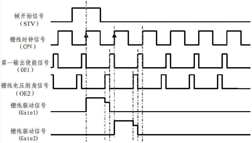
[0057] Further, in the driving method described in the embodiment of the present invention, when the voltage of the shielding signal is at a high level, the first output enable signal is pulled to a high level.

[0058] Fi...


PUM


Abstract

The invention discloses a display drive circuit which comprises a grid line drive circuit, a shielding signal generation circuit and a grid line shielding circuit, wherein the grid line drive circuit is used for separating grid line drive signals of adjacent rows according to a first output enable signal; the shielding signal generation circuit triggers to generate a shielding signal when the grid line drive signals need to be turned off; a first input end of the grid line shielding circuit inputs a first output enable signal, a second input end of the grid line shielding circuit inputs the shielding signal, and an output end of the grid line shielding circuit is connected with the grid line drive circuit; and the grid line shielding signal is used for shielding the first output enable signal according to the shielding signal so as to turn off the grid line drive signal. According to the display drive circuit and the drive method thereof as well as the display device disclosed by the invention, the first output enable signal is shielded directly according to the shielding signal so as to turn off the grid line drive signal and shield the data on corresponding grid line; and display anomaly can be avoided by use of the first output enable signal, and the circuit cost and the circuit space also can be saved.

Description

technical field [0001] The present invention relates to the field of display technology, in particular to a display driving circuit, a driving method thereof, and a display device. Background technique [0002] The display device drives the panel (panel) to work by outputting specific control signals through the timing controller. The timing controller usually includes the following signals: frame start signal (STV), gate line clock signal (CPV), and the first output enables Enable signal (OE1, Output Enable), gate line voltage clipping signal (OE2), data read-in and output signal (TP), pixel polarity control signal (POL), data enable signal (DE, Data Enable). The signals STV, CPV, OE1 and OE2 jointly control and drive the gate lines of the array substrate of the display device; the rising edge of the CPV signal triggers and drives each gate line, and through the shift register, the gate line driving signals of each gate line are sequentially triggered ; The OE1 signal is u...

Claims


Application Information

Patent Timeline
Patent Type & Authority Applications(China)
IPC IPC(8): G09G3/20
CPCG09G3/20G09G2310/0213G09G2310/0286G09G2320/0209G09G2320/0247G11C19/28
Inventor 吴行吉李承珉许益祯张亮
Owner BOE TECH GRP CO LTD
Why Eureka
Try Eureka