
Antenna device and mobile terminal

An antenna device and antenna technology, applied in the field of communication, can solve problems such as the influence of antenna radio frequency performance, and achieve the effect of wide antenna bandwidth

Active Publication Date: 2017-03-29
NUBIA TECHNOLOGY CO LTD
View PDF4 Cites 0 Cited by
  • Summary
  • Abstract
  • Description
  • Claims
  • Application Information

AI Technical Summary

Problems solved by technology

[0003] The purpose of the embodiments of the present invention is to provide an antenna device and a mobile terminal, which aims to solve the problem that the conductive surface shell of the existing mobile terminal has a negative impact on the radio frequency performance of the antenna, and at the same time reduce the impact of the hand on the antenna

Method used


Image

  • Antenna device and mobile terminal
  • Antenna device and mobile terminal

Examples


Embodiment 1

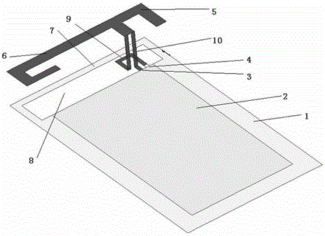
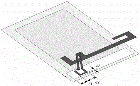
[0033] Embodiment 1 of the present invention proposes an antenna device applied to a mobile terminal. The mobile terminal includes a conductive surface case 1 and a main board 2. The main board 2 is placed on or embedded in the conductive surface case 1 of the mobile terminal. Since the main board 2 and the main board 2 The conductive surface shell 1 is in contact to form an electrical connection, so the main board 2 and the conductive surface shell 1 form a complete conductor, and the conductive surface shell 1 can be a conductor of suitable material such as various metal conductors. like figure 1 As shown, the antenna device according to Embodiment 1 of the present invention includes an annular metal region 8 , an antenna main body, a first feed terminal and a second feed terminal.

[0034] The metal area 8 is a metal frame hollow area, which can be arranged on the main board 2 or the conductive surface case 1, or as figure 1 As shown, it consists of a main board 2 and a co...

Embodiment 2

[0047] Embodiment 2 of the present invention proposes a mobile terminal, including a conductive cover, a main board, and an antenna device. The structure and working principle of the antenna device are similar to those of the antenna device in Embodiment 1 of the present invention, and will not be repeated here.


PUM


Abstract

The invention is applied to the communication field and provides an antenna device and a mobile terminal. The antenna device comprises an annular metal area, an antenna main body, a first feed terminal and a second feed terminal, wherein the metal area, and a conductive surface shell and a main board of the mobile terminal form an integral conductor; the antenna main body is arranged above the metal area, coupled with a frame of the metal area and used for generating one or more frequency resonance points; the first feed terminal and the second feed terminal are in bridge connection via the main board; the first feed terminal is connected to an earth wire of the main board; and the second feed terminal is connected to a signal wire of the main board. According to the antenna device and the mobile terminal disclosed by the invention, the radio-frequency performance of an antenna can be improved.

Description

technical field [0001] The invention belongs to the communication field, and in particular relates to an antenna device and a mobile terminal. Background technique [0002] Mobile terminals pay more and more attention to user experience. The metal face shell can bring a good texture, but the metal face shell itself has a great impact on the antenna. To solve this problem, many current technologies are to cut a breakpoint on the metal frame , this design will generally affect the appearance of the mobile terminal, and the structural reliability design is relatively difficult. At present, there is another technology to add a feed ground point in the middle of the metal shell. This technology has relatively large constraints. The feed ground point needs to be in the middle of the metal shell, and the metal shell itself does not generate a resonance point. The shell is simply an extension of the antenna body. Contents of the invention [0003] The purpose of the embodiments ...

Claims


Application Information

Patent Timeline
Patent Type & Authority Patents(China)
IPC IPC(8): H01Q1/44H01Q1/24H01Q5/10
Inventor 程仕意
Owner NUBIA TECHNOLOGY CO LTD
Learn More