
Monopole antenna

A monopole antenna and support technology, applied in the field of antennas, can solve the problems of increasing the size of the antenna, affecting the efficiency of the antenna, and difficult to achieve the minimization of the antenna.

Inactive Publication Date: 2013-06-26
ARCADYAN
View PDF5 Cites 0 Cited by
  • Summary
  • Abstract
  • Description
  • Claims
  • Application Information

AI Technical Summary

Problems solved by technology

Therefore, some monopole antennas have been proposed in the prior art, such as U.S. Patent No. 7,327,327 and No. 7,148,848. Both inventions must add supports to fix and support the monopole antenna, otherwise the radiating part of the antenna is easy to produce vertical and horizontal directions due to weight. Tilted and deformed, thereby affecting the performance of the antenna
However, the size of the antenna is increased due to the additional support structure, which not only makes it difficult to achieve the goal of minimizing the antenna, but also increases the cost of antenna production.
Under such constraints, it is bound to be quite limited to design a monopole antenna with high gain, small size, wide frequency band and excellent radiation pattern.

Method used


Image

  • Monopole antenna
  • Monopole antenna
  • Monopole antenna

Examples


Embodiment Construction

[0021] The "monopole antenna" proposed in this case will be fully understood by the following examples, so that those who are familiar with the art can complete it. However, the implementation of this case cannot be limited by the following examples. Those skilled in the art can still derive other embodiments based on the spirit of the disclosed embodiments, and these embodiments all belong to the scope of the present invention.

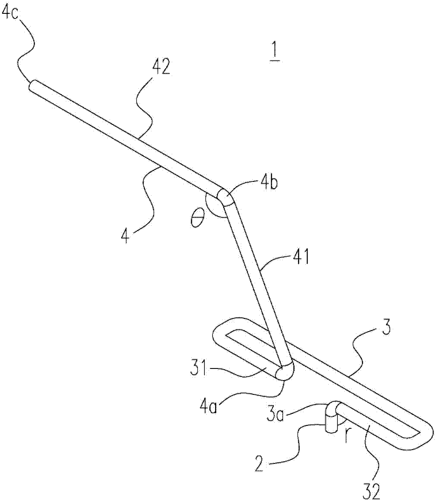
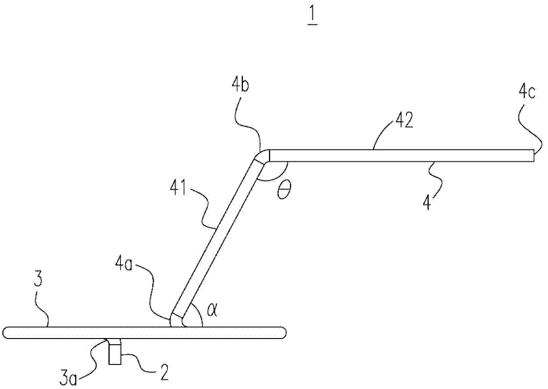
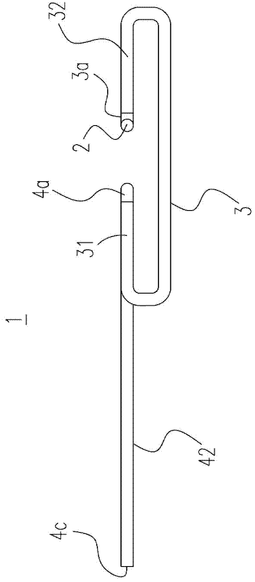
[0022] see figure 1 . figure 1 It is a perspective view of a monopole antenna 1 according to an embodiment of the present invention. The monopole antenna 1 is made of a conductor material, preferably a metal conductor material, and each component of the monopole antenna 1 is integrally formed. The main components of the monopole antenna 1 include a supporting part 3 and a radiating part 4 . The support part 3 is located on the first plane (not shown in the figure), preferably formed in an unclosed ring shape (resembling a rectangle in this embodim...


PUM


Abstract

The invention provides a monopole antenna which comprises a signal feeding portion, a radiation portion and a support portion connected with the signal feeding portion and the radiation portion. A first angle is formed by the radiation portion and the support portion and extends from the support portion, and a second angle is formed by the signal feeding portion and the support portion and extends from the support portion.

Description

technical field [0001] The present invention relates to an antenna, and in particular to a monopole antenna. Background technique [0002] In recent years, affected by the popularization of wireless communication devices such as mobile phones, notebook computers and even wireless access points (APs), antennas used to send and receive electronic signals have also received attention, especially antennas with simple structures are more popular in the market, among which monopole The antenna has attracted attention because it is one of the antennas with the simplest structure. [0003] Due to the requirement for a small-sized wireless device, its antenna size must be minimized to be applicable. Therefore, some monopole antennas have been proposed in the prior art, such as U.S. Patent No. 7,327,327 and No. 7,148,848. Both inventions must add supports to fix and support the monopole antenna, otherwise the radiating part of the antenna is easy to produce vertical and horizontal di...

Claims


Application Information

Patent Timeline
Patent Type & Authority Applications(China)
IPC IPC(8): H01Q1/36
Inventor 黄智勇罗国彰杜健志
Owner ARCADYAN
Learn More