
Electric-control switching multi-polarization horn antenna

A horn antenna and electronic control technology, which is applied to antennas, waveguide horns, circuits, etc., can solve problems such as increasing the difficulty of testing for testers, and achieve the effects of reducing the number of antenna replacements, high reliability, and wide antenna bandwidth

Pending Publication Date: 2019-03-08
胡南
View PDF0 Cites 1 Cited by
  • Summary
  • Abstract
  • Description
  • Claims
  • Application Information

AI Technical Summary

Problems solved by technology

At present, several antennas with known polarization directions are mostly used to test and measure or receive electromagnetic field signals. In the actual process, testers need to constantly replace the test antennas and require different calibrations, which increases the test personnel. test difficulty

Method used

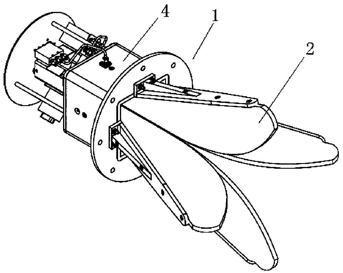
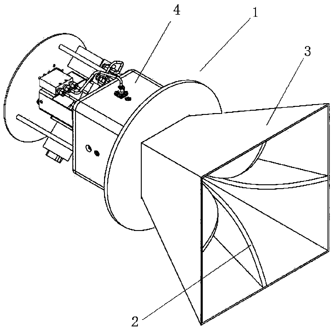
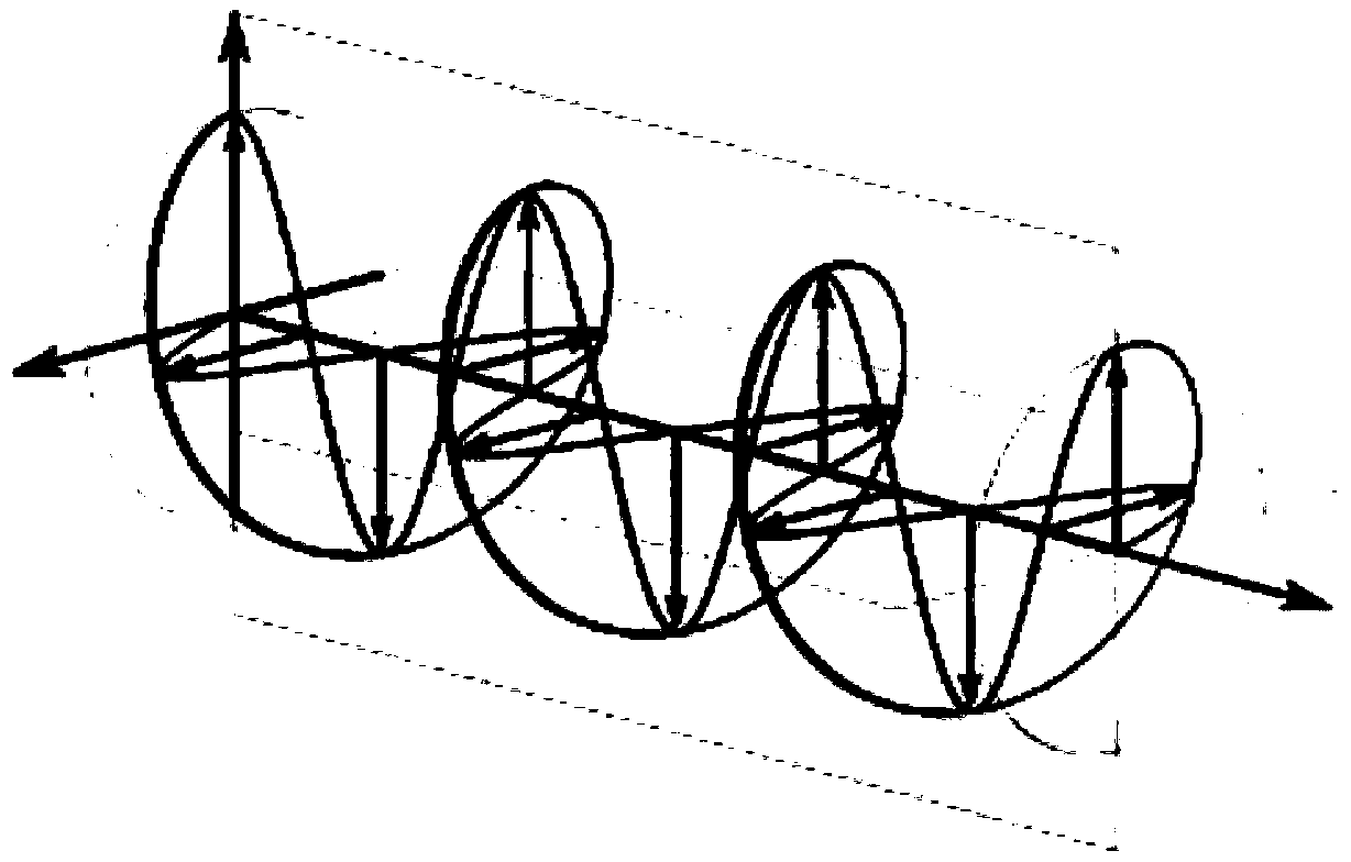

Image

  • Electric-control switching multi-polarization horn antenna
  • Electric-control switching multi-polarization horn antenna
  • Electric-control switching multi-polarization horn antenna

Examples


Embodiment Construction

[0028] The technical solutions in the embodiments of the present invention are clearly and completely described below in conjunction with the accompanying drawings in the embodiments of the present invention. Obviously, the described embodiments are only part of the embodiments of the present invention, not all of them. Based on the embodiments of the present invention, all other embodiments obtained by persons of ordinary skill in the art without making creative efforts belong to the protection scope of the present invention.

[0029] In the following description, a lot of specific details are set forth in order to fully understand the present invention, but the present invention can also be implemented in other ways different from those described here, and those skilled in the art can do it without departing from the meaning of the present invention. By analogy, the present invention is therefore not limited to the specific examples disclosed below.

[0030] Such as figure ...


PUM


Abstract

The invention discloses an electric-control switching multi-polarization horn antenna, and relates to the technical field of a communication antenna. The horn antenna comprises a horn antenna body andalso comprises a polarization controller and a polarization switching device, wherein the control module is used for enabling the horn antenna to work in modes of horizontal polarization, vertical polarization, left-hand circular polarization or right-hand circular polarization by controlling a linear polarization control generation module, a circular polarization control generation module and apolarization selection module. By the antenna, rapid switching among different polarization modes can be achieved, and switching employs electric switching rather than artificial antenna replacement.With the adoption of the antenna, the test time can be effectively reduced, the frequency of replacing the antenna by a tester is reduced, and the characteristic of a tested device under various polarization modes is more accurately measured.

Description

technical field [0001] The invention relates to the technical field of communication antennas, in particular to an electrically controlled switching multi-polarization horn antenna. Background technique [0002] An antenna is an electromagnetic field energy converter that converts a guided wave propagating on a transmission line into an electromagnetic wave propagating in an unbounded medium (usually free space), or vice versa. It belongs to the core component used to transmit or receive electromagnetic waves in radio equipment. Engineering systems such as radio communication, broadcasting, television, radar, navigation, electronic countermeasures, remote sensing, and radio astronomy, which use electromagnetic waves to transmit information, need to rely on antennas to work. In addition, in terms of transmitting energy with electromagnetic waves, non-signal energy radiation also requires antennas. [0003] The direction of the electric field and the direction of the magneti...

Claims


Application Information

Patent Timeline
IPC IPC(8): H01Q13/02H01Q15/24H01P1/16
CPCH01P1/16H01Q13/02H01Q15/24H01Q15/242
Inventor 胡南
Owner 胡南
Learn More