
Antenna structure and electronic equipment

An antenna structure and antenna technology, applied in the field of communication, can solve problems such as large differences and different antenna performance, and achieve the effects of natural performance balance, small antenna loss, and wide antenna bandwidth

Inactive Publication Date: 2019-04-16
HUIZHOU TCL MOBILE COMM CO LTD
View PDF8 Cites 0 Cited by
  • Summary
  • Abstract
  • Description
  • Claims
  • Application Information

AI Technical Summary

Problems solved by technology

[0003] In the antenna design of conventional electronic devices, it is inevitable to face a problem. When holding the mobile phone with the left hand, the performance of the antenna is not the same as when holding the mobile phone with the right hand, and usually the difference is very large.

Method used


Image

  • Antenna structure and electronic equipment
  • Antenna structure and electronic equipment
  • Antenna structure and electronic equipment

Examples


Embodiment Construction

[0020] The following will clearly and completely describe the technical solutions in the embodiments of the present invention with reference to the accompanying drawings in the embodiments of the present invention. Obviously, the described embodiments are only some, not all, embodiments of the present invention. Based on the embodiments of the present invention, all other embodiments obtained by those skilled in the art without creative efforts fall within the protection scope of the present invention.

[0021] In this application, the word "exemplary" is used to mean "serving as an example, illustration or illustration". Any embodiment described in this application as "exemplary" is not necessarily to be construed as preferred or advantageous over other embodiments. The following description is given to enable any person skilled in the art to make and use the invention. In the following description, details are set forth for purposes of explanation. It should be understood ...


PUM


Abstract

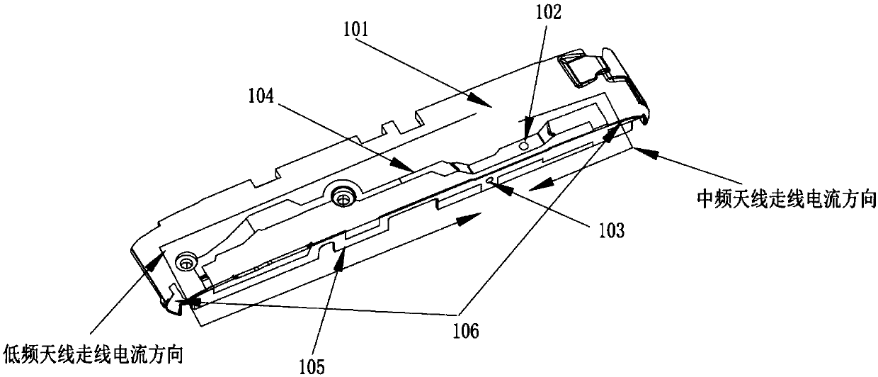
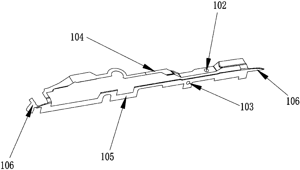
The embodiment of the invention discloses an antenna structure and a piece of electronic equipment. The antenna structure includes an antenna support. Antenna lines are arranged on one side of the antenna support. The antenna lines include two loop lines used to realize low and intermediate frequencies respectively, and a high-frequency antenna line is arranged beside the two loop lines and at theedge of the support. In the embodiment of the invention, the antenna lines are based on the loop antenna line principle but different from the conventional single loop line, two loop antennas are used to realize low-frequency and intermediate-frequency functions respectively, and wider antenna bandwidth and higher efficiency are achieved. Meanwhile, because the overall loop antenna lines are closed, the antenna loss caused by antenna holding by hands is small, and the left-hand and right-hand antenna performances are more balanced.

Description

technical field [0001] The invention relates to the technical field of communication, in particular to an antenna structure and electronic equipment. Background technique [0002] As electronic devices such as mobile phones and tablet computers are more and more widely used in people's daily life, people are constantly putting forward new requirements for the structure and functions of electronic devices, such as requiring smaller device specifications and larger screen occupation. Metal shell with better hand feeling. Under the requirements of this design concept, more and more devices will be placed in the antenna area, resulting in an increasingly complex space environment for the antenna. In a limited space environment, it is difficult to design a mobile phone antenna that meets the requirements of multiple frequency bands. [0003] In the antenna design of conventional electronic devices, it is inevitable to face a problem. When the mobile phone is held in the left ha...

Claims


Application Information

Patent Timeline
IPC IPC(8): H01Q1/12H01Q1/50
CPCH01Q1/12H01Q1/50
Inventor 陈卫叶嘉宾陈志伟
Owner HUIZHOU TCL MOBILE COMM CO LTD
Learn More