Drawer position device of low-voltage switchgear cabinet

A low-voltage switchgear and drawer technology, applied in switchgear, pull-out switchgear, electrical components, etc., can solve the problems of inability to ensure correctness, poor reliability, complex structure, etc., and achieve the effect of simple structure

Active Publication Date: 2013-06-26
SCHNEIDER ELECTRIC CHINA
View PDF4 Cites 9 Cited by
  • Summary
  • Abstract
  • Description
  • Claims
  • Application Information

AI Technical Summary

Problems solved by technology

Therefore, most low-voltage switchgears currently adopt this method. There are currently various structures for inserting and withdrawing drawers. Some structures are too complicated, and the reliability is not good. The correctness of the position display cannot be guaranteed. Therefore, a simple structure is required. However, it can clearly display the device of each position. The combination of mechanical and position sensors can effectively display the specific position of the drawer on the panel, so as to avoid accidents caused by misoperation.

Method used


Image

  • Drawer position device of low-voltage switchgear cabinet
  • Drawer position device of low-voltage switchgear cabinet
  • Drawer position device of low-voltage switchgear cabinet

Examples


Embodiment Construction

[0013] The present invention will be further described below in conjunction with specific drawings.

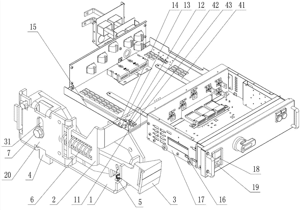
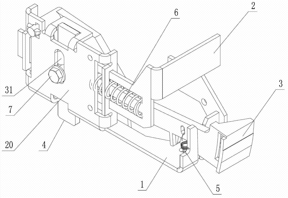
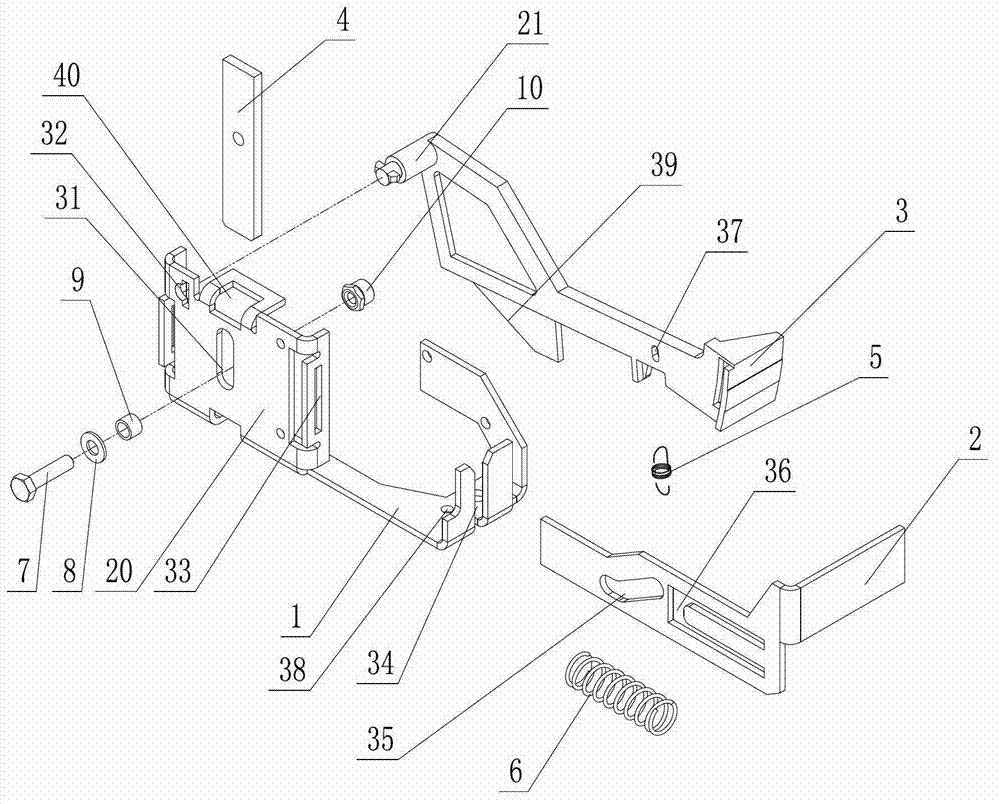
[0014] Such as Figure 1 ~ Figure 3 As shown: the drawer position device of the low-voltage switch cabinet includes a bracket 1, a slider 2, a display rod 3, a pin plate 4, a return spring 5, a push spring 6, a fixing screw 7, a washer 8, a ball 9, a fixing nut 10, Drawer positioning block 11, isolation sensor 12, test sensor 13, working sensor 14, drawer partition 15, sensor baffle 16, drawer 17, position lock button 18, position display window 19, mounting plate 20, positioning pin 21, chute 31. Positioning hole 32, position slot 33, positioning slot 34, chute 35, circlip slot 36, hook hole 37, hook shaft 38, inclined sliding surface 39, pin plate socket 40, guide rail 41, pin plate positioning slot 42 , Inclined block 43 etc.

[0015] Such as figure 1 Shown, the present invention comprises the drawer dividing plate 15 that is installed on the low-voltage switchgear, guid...


PUM


Abstract

The invention relates to a drawer position device of a low-voltage switchgear cabinet. The drawer position device comprises a drawer clapboard and a drawer and is characterized in that a pushing mechanism is arranged at the inner side of the drawer, and a position locking button and a position display window are arranged at the outer side of the drawer; the pushing mechanism comprises a bracket and a sliding block, wherein a mounting plate is fixed on the bracket, the sliding block is arranged on the mounting plate, the sliding block is in contact with the position locking button, and the side part of the sliding block is provided with an inclined chute; the mounting plate is provided with a sliding chute, and the upper part of the mounting plate is inserted into a pin board; a fastening screw is arranged in each of the inclined chute and the sliding chute, the fastening screws are connected with the pin board, and a pin board positioning slot is arranged at the bottom of the drawer clapboard; a clamp spring slot is arranged at the side part of the sliding block, and a pushing spring is arranged in the clamp spring slot; a display pole is arranged on the bracket, a reset spring is connected between the display pole and the bracket, and the end part of the display pole is rotatably connected with the mounting plate; and an inclined sliding surface is arranged at the bottom of the display pole, and the inclined sliding surface is in contact with and matched with an inclined block at the bottom of the drawer clapboard. According to the drawer position device, three positions, namely, isolation, test and working of the drawer can be effectively displayed.

Description

technical field [0001] The invention relates to a position device, in particular to a drawer position device of a low-voltage switch cabinet. Background technique [0002] Low-voltage switchgear is one of the most used equipment in power transmission and distribution equipment. In low-voltage switchgear, in order to ensure the reliability of equipment and shorten maintenance time, the drawer-type installation method can effectively solve the problem of low-voltage switchgear. and shorten the maintenance time, because the drawer has strong versatility and good interchangeability, it can be replaced at any time in case of failure. Therefore, most low-voltage switchgears currently adopt this method. There are currently various structures for inserting and withdrawing drawers. Some structures are too complicated, and the reliability is not good. The correctness of the position display cannot be guaranteed. Therefore, a simple structure is required. But it can also clearly displ...

Claims


Application Information

Patent Timeline
Patent Type & Authority Applications(China)
IPC IPC(8): H02B11/173H02B11/127
Inventor 秦科君
Owner SCHNEIDER ELECTRIC CHINA
Why Eureka
Try Eureka