Vector magnetic fluid motor based on phase angle controlling

A phase angle control and vector technology, which is applied in the direction of single motor speed/torque control, electrical components, electromechanical devices, etc., can solve the problems of the overall conversion efficiency loss of electrical energy and mechanical energy, so as to improve the output effect of mechanical energy and energy conversion efficiency , Optimize the effect of the magnetic circuit

Inactive Publication Date: 2015-05-13
江苏飞马动力科技有限公司
View PDF6 Cites 0 Cited by
  • Summary
  • Abstract
  • Description
  • Claims
  • Application Information

AI Technical Summary

Problems solved by technology

In the engineering design of traditional motors, part of the beneficial effects of electrical characteristics and mechanical energy characteristics are actually sacrificed, resulting in the loss of the overall conversion efficiency of electrical energy and mechanical energy.

Method used


Image

  • Vector magnetic fluid motor based on phase angle controlling
  • Vector magnetic fluid motor based on phase angle controlling
  • Vector magnetic fluid motor based on phase angle controlling

Examples


Embodiment 1

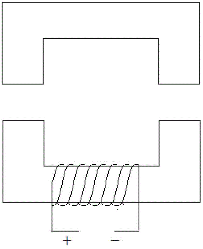
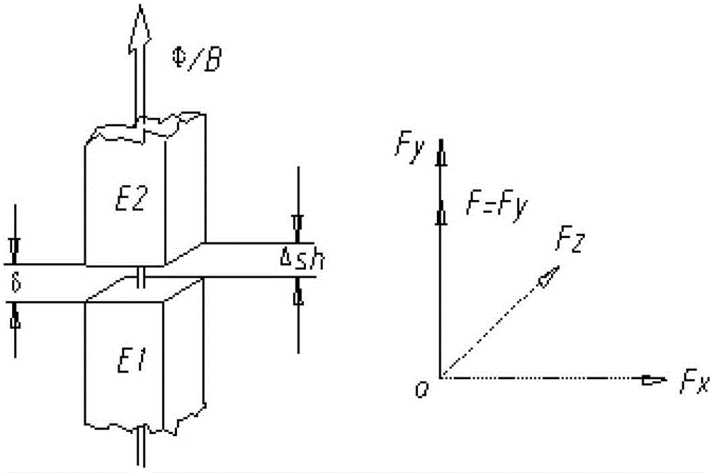
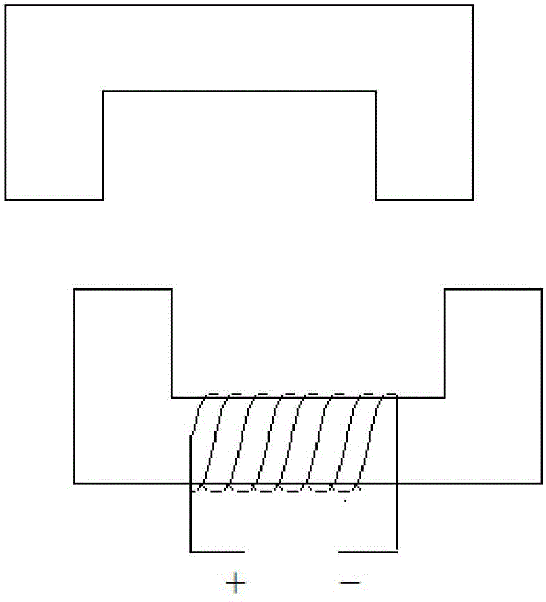
[0124] Such as Figure 1a , The stator magnet E1 and the mover magnet E2 are coaxially arranged, there is an air gap δ between the stator magnet E1 and the mover magnet E2, the stator magnet E1 is fixed, the mover magnet E2 can be in the y-axis direction To move, the controller only needs to input electrical energy to the closed coil in the stator magnetizer E1 or the mover magnetizer E2 mechanism to move the mover magnetizer E2 upward by Δs h . When the mover magnetizer E2 has completed Δs h During the stroke, the controller cuts off the input current, and the mover magnetizer E2 returns to the initial position, ready for the next mechanical movement and work cycle, until the controller sends out work instructions and input electrical energy again. The mechanical movement feature of the mover magnetizer E2 mechanism is a simple, linear, reciprocating mechanical movement.

[0125] Refer to Figure 1a , 1b And 2a, 2b: When the current is input to the closed coil, the magnetic flux...

Embodiment 2

[0132] See attached Figure 5A , A vector magnetic current motor based on phase angle control, composed of stator 6, mover 7 and controller 5. A stator magnet 1 is provided on the stator 6, a winding coil 2 is provided on the stator magnet 1, a mover magnet 3 is provided on the mover 7, and an air gap is provided between the stator guide 6 and the mover magnet 3. δ4, stator magnet 1, mover magnet 3 and air gap δ4 constitute a magnetic flux circuit 8. The stator 6 is in a fixed position, and the mover magnetizer 3 is a mechanical movement that can rotate and move along the circle center O and the radius R. The controller 5 is connected to the winding coil 2, and the winding coil 2 is connected to the controller 5. The controller 5 controls the on / off of the connection between the winding coil 2 and the main power supply. The stator 6 is provided with a position sensor 9, and the position sensor 9 outputs the current change amount ΔS of the winding coil 2 to the controller 5.

[...

Embodiment 3

[0139] Such as Figure 7 As shown, the difference between this embodiment and the second embodiment is that the mover 7 is provided with the first to fourth four mover magnetizers 3a, 3b, 3c, 3d, and the controller 5 controls the energization frequency of the winding coil 2. , Control the speed of the motor.


PUM


Abstract

A vector magnetic fluid motor based on phase angle controlling comprises a stator, a rotor and a coil. The stator is arranged opposite to the rotor; the stator is fixed; and the rotor can move relatively to the stator. At least one stator magnetizer is arranged in the stator; and at least one rotor magnetizer is arranged in the rotor. An air gap is arranged between the stator magnetizer and the rotor magnetizer. The coil is wound on the stator magnetizer and the rotor magnetizer. A position sensor and a controller are arranged, and the position sensor is connected with the controller; and the coil is connected with a power source through the controller. Totally different working principles and working manners are adopted on the vector magnetic fluid motor; two working manners of magnetic field rotating and phase shifting of traditional motors are completely abandoned; inductive reactance is basically eliminated; impedance is drastically reduced; and remarkable energy-saving effect is achieved. The vector magnetic fluid motor has fire-new structure and working manners.

Description

Technical field [0001] The invention belongs to the field of electrical energy and mechanical energy conversion, and specifically relates to a vector magnetic current motor based on phase angle control (also referred to as "a vector magnetic current motor based on phase angle control"). Background technique [0002] The widely used motor is a classic electrical and mechanical energy conversion device. Due to the limited operation mode and structure of this traditional motor, the conversion efficiency of electrical and mechanical energy is difficult to further improve. This is because: a. The traditional motor uses AC and DC or single-phase and multi-phase electrical energy input forms , The direction and intensity of the current in the coil winding have been changing, and the "inductive" characteristics of the coil winding make it impossible to avoid the loss caused by the "inductive reactance". b. As a traditional motor in rotating operation mode, the "pole shoes" between the s...

Claims


Application Information

Patent Timeline
Patent Type & Authority Patents(China)
IPC IPC(8): H02K11/00H02P6/08H02P6/16H02K11/21
Inventor 王宏喜钱裕盛姚飞
Owner 江苏飞马动力科技有限公司
Why Eureka
Try Eureka