Actuating mechanism of mechanical shearing machine

A technology of executive mechanism and shearing machine, which is applied to shearing equipment, shearing devices, metal processing equipment, etc., can solve the problems of short shearing stroke and increased production cost, so as to improve forming quality, increase production efficiency, reduce The effect of production costs

Inactive Publication Date: 2015-08-12
DALIAN UNIV OF TECH
View PDF5 Cites 3 Cited by
  • Summary
  • Abstract
  • Description
  • Claims
  • Application Information

AI Technical Summary

Problems solved by technology

Although the structure of the centering crank slider mechanism is simple and the manufacturing cost is low, the speed curve of the centering crank slider mechanism is close to a sinusoidal curve. When driving the inclined blade cutter to shear the plate, the speed changes greatly at different positions, and the quality of the incision is not uniform. It is often necessary to increase the process to process the incision, which greatly increases the production cost; in addition, the centering crank slider mechanism has no quick return characteristics, and the shearing plate can be used with a short stroke

Method used


Image

  • Actuating mechanism of mechanical shearing machine
  • Actuating mechanism of mechanical shearing machine
  • Actuating mechanism of mechanical shearing machine

Examples


Embodiment Construction

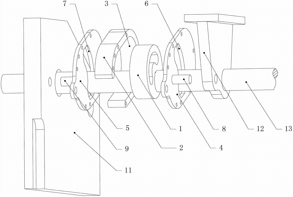
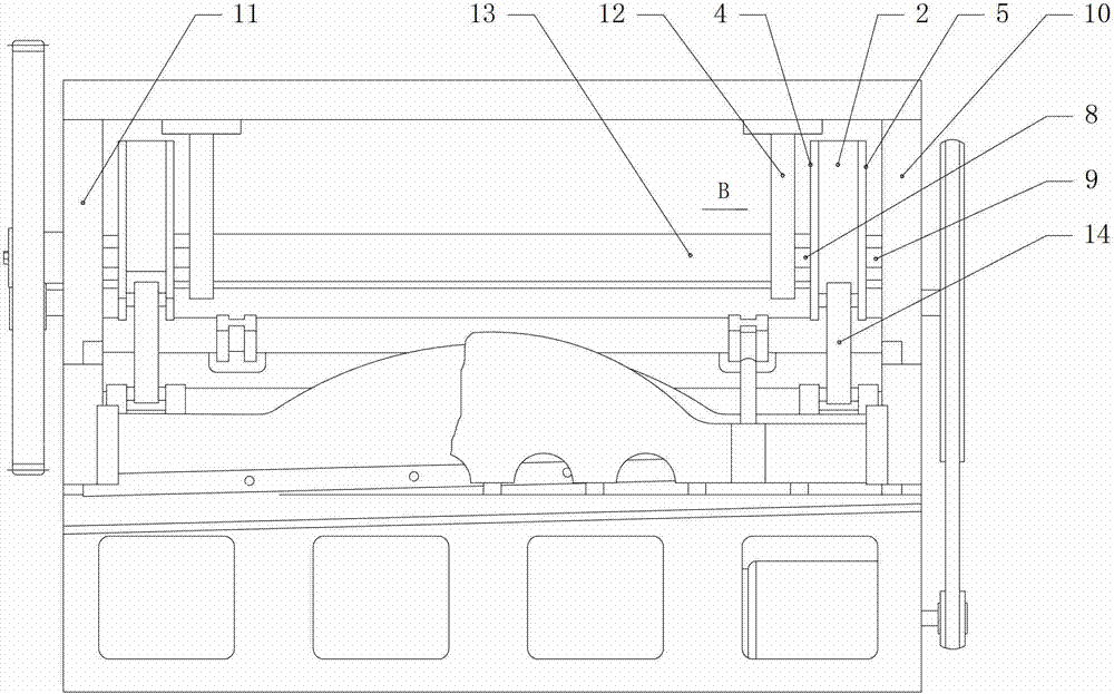
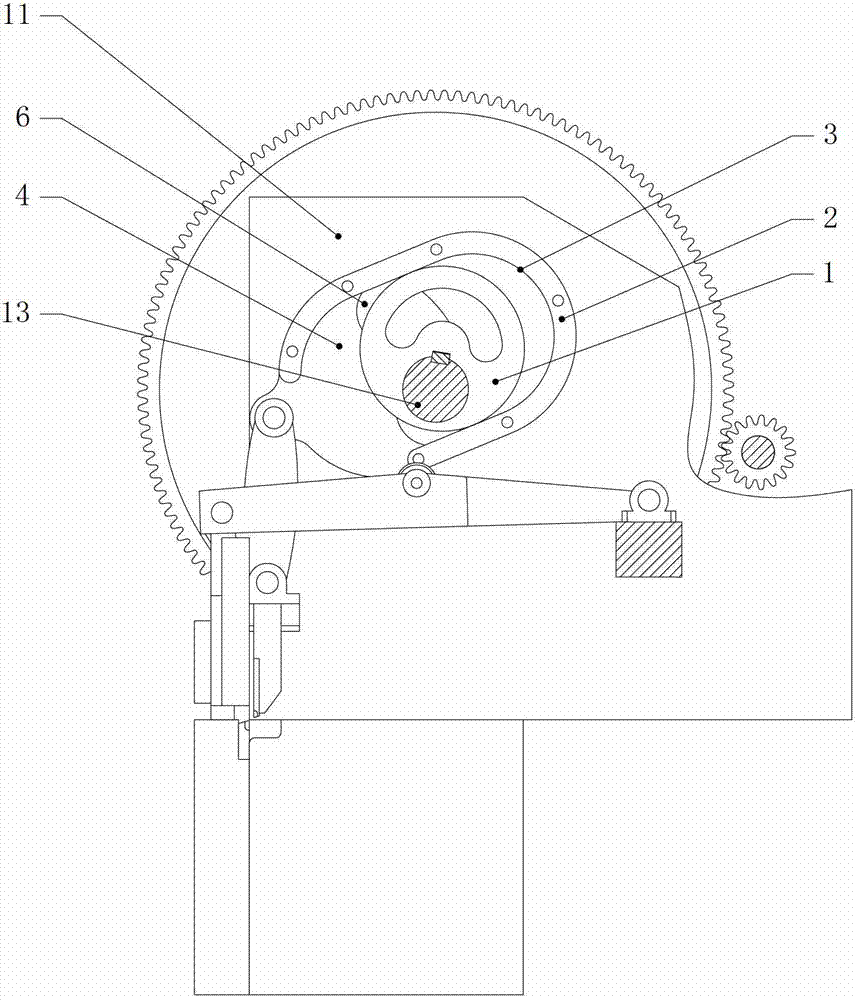
[0018] The specific embodiment of the present invention is shown in the accompanying drawings, which is characterized in that the actuator includes an eccentric wheel 1, a pendulum block housing 2, an eccentric wheel groove 3, a sealing cover I4, a sealing cover II5, an arc-shaped main shaft groove I6, an arc Shaped main shaft groove II7, rotating shaft I8, rotating shaft II9; eccentric wheel 1 is symmetrically installed on the main shaft 13 between the side support I10 and the T-frame 12 of the shearing machine and between the side support II11 and the T-frame 12, and the eccentric The connection mode between the wheel 1 and the main shaft 13 is a key connection; the inside of the pendulum block housing 2 is processed with an eccentric wheel groove 3, the eccentric wheel 1 is placed in the eccentric wheel groove 3, and is connected with the eccentric wheel groove 3 by sliding friction; the sealing cover I4 and the sealing cover II5 are respectively fixed on both sides of the p...


PUM


Abstract

The invention discloses an executing mechanism of a mechanical plate shearing machine and relates to the executing mechanism used on a mechanical plate shearing machine. The executing mechanism of the mechanical plate shearing machine is characterized in that eccentric wheels are symmetrically arranged on a main shaft between the side bracket of the plate shearing machine and the T-shaped frame; an eccentric wheel slot is machined on the inner part of a swinging block shell; the eccentric wheels are placed in the eccentric wheel slot and connected with the eccentric wheel slot in a sliding friction manner; two sealing covers are fixed at the two sides of the swinging block shell, respectively; arc-shaped main shaft slots are machined on the sealing covers; the main shaft slides in the arc-shaped shaft slots relative to the sealing covers; narrow ends of the sealing covers are hinged with the upper end of a connecting rod on the plate shearing machine; one end of a rotor I is fixed at the outer sides of the sealing covers; and the other ends of the rotator I are hinged with the lower end of the T-shaped frame on the plate shearing machine. The executing mechanism of the mechanical plate shearing machine has the characteristics of being novel in structure, simple to modify, low in cost, safe and reliable, good in economical efficiency and safety and the like, and therefore, the executing mechanism of the mechanical plate shearing machine is integrated with economical efficiency and practicability.

Description

technical field [0001] The actuator of the mechanical shearing machine described in the present invention relates to an actuator used on the mechanical shearing machine. Background technique [0002] The current mechanical shearing machine uses a centering crank slider mechanism as an actuator, the main shaft drives the eccentric wheel to rotate, and the connecting rod drives the cutter to perform shearing motion. Although the structure of the centering crank slider mechanism is simple and the manufacturing cost is low, the speed curve of the centering crank slider mechanism is close to a sinusoidal curve. When driving the oblique blade cutter to shear the plate, the speed changes greatly at different positions, and the quality of the incision is not uniform. It is often necessary to increase the process to process the incision, thereby greatly increasing the production cost; in addition, the centering crank slider mechanism has no quick return characteristic, and the availa...

Claims


Application Information

Patent Timeline
Patent Type & Authority Patents(China)
IPC IPC(8): B23D15/12B23D15/06
Inventor 张明恒郑雨姚宝珍周俊
Owner DALIAN UNIV OF TECH
Why Eureka
Try Eureka