Turbine rotor blade, rotating assembly and turbine engine

A technology for turbine rotors and rotating components, applied in engine components, machines/engines, blade support components, etc., can solve the problems of stress concentration, reduced service life of turbine rotor blades, large amount of cantilever in local structures, etc., to achieve machinability improved effect

Active Publication Date: 2013-07-03
AECC COMML AIRCRAFT ENGINE CO LTD
View PDF7 Cites 4 Cited by
  • Summary
  • Abstract
  • Description
  • Claims
  • Application Information

AI Technical Summary

Problems solved by technology

However, it is obvious that such a blade shroud with a Z-shaped profile is difficult to machine, and in addition, the mass distribution is not uniform resulting in a large local structure cantilever and causing stress concentrations, thus reducing the service life of the turbine rotor blades

Method used


Image

  • Turbine rotor blade, rotating assembly and turbine engine
  • Turbine rotor blade, rotating assembly and turbine engine
  • Turbine rotor blade, rotating assembly and turbine engine

Examples


Embodiment Construction

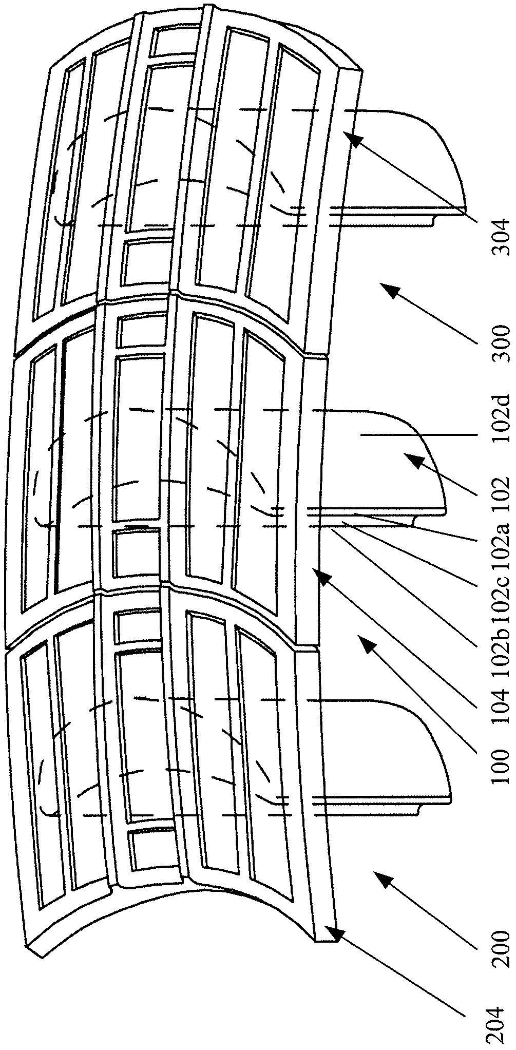
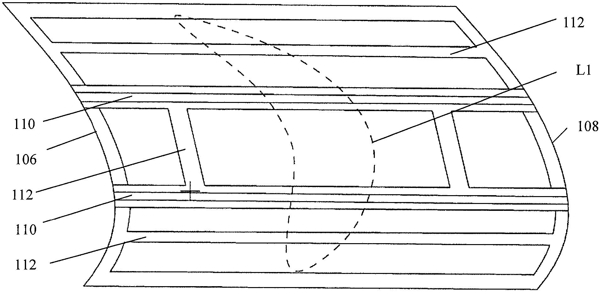
[0021] Such as figure 1 and figure 2 As shown, among them, figure 1 A schematic diagram showing three turbine rotor blades arranged adjacently in pairs, figure 2 for figure 1 A schematic diagram of the shroud portion of a turbine rotor blade. The three turbine rotor blades are represented by reference numerals 100, 200 and 300 respectively. The turbine rotor blade shown in the figure is a preferred embodiment of the present invention. Below, one of the turbine rotor blades 100 is taken as an example for illustration . Turbine rotor blade 100 includes an airfoil portion 102 and a shroud portion 104 . Wherein, the airfoil portion 102 has a blade leading edge 102a, a blade trailing edge 102b, a pressure surface 102c, and a suction surface 102d; 102, which has a shroud leading edge 106 and a shroud trailing edge 108. Here, the airfoil portion 102 and the shroud portion 104 are integrally formed. Both the front edge 106 of the shroud and the trailing edge 108 of the shrou...


PUM


Abstract

The invention relates to a turbine rotor blade, which comprises a wing-shaped part and a blade crown part, wherein the blade crown part is formed on the free end of the wing-shaped part through generally, circumferentially and axially extending along the center of a turbine rotor, and is provided with a blade crown front edge and a blade crown back edge, wherein the blade crown front edge and the blade crown back edge are respectively in smoothly transited arc shapes. The blade crown front edge and the blade crown back edge are designed into arc shapes, the processibility of the blade crown part can be improved, and meanwhile, the weight distribution of the blade crown part can be more uniform through the arc-shaped blade crown front edge and the arc-shaped blade crown back edge, so the stress concentration effect is reduced.

Description

technical field [0001] The invention relates to a turbine rotor blade, a rotating assembly and a turbine engine. Background technique [0002] Gas turbines are used in many fields to drive electrical generators or working machines, especially in aircraft. Here, the energy of the fuel is used to rotate the turbine shaft. For this purpose, the fuel is burned in a combustion chamber into which the air compressed by the compressor is also fed. In the combustion chamber, the high-temperature and high-pressure working medium formed by the combustion of fuel expands and works through a turbine unit connected behind the combustion chamber. [0003] Turbine rotor blades are an important component in a turbine unit for converting thermal energy from the combustion chamber into mechanical work for the turbine rotor. Turbine performance can be enhanced by sealing the turbine blade tips, preventing combustion gases from escaping from the airflow into the gap between the blade tips and...

Claims


Application Information

Patent Timeline
Patent Type & Authority Applications(China)
IPC IPC(8): F01D5/14
Inventor 陈亚龙万明学齐晓东
Owner AECC COMML AIRCRAFT ENGINE CO LTD
Why Eureka
Try Eureka