Forecasting method for loop length of hot continuous rolling mill

A hot continuous rolling mill and looper technology, which is applied in metal rolling, metal rolling, tension/pressure control, etc., can solve problems such as narrowing of the strip head, high looper tension, abnormal looper control, etc., and achieve Stabilize the wearing of the belt, avoid the effect of pulling up and narrowing

Active Publication Date: 2013-07-10
BAOSHAN IRON & STEEL CO LTD
View PDF7 Cites 10 Cited by
  • Summary
  • Abstract
  • Description
  • Claims
  • Application Information

AI Technical Summary

Problems solved by technology

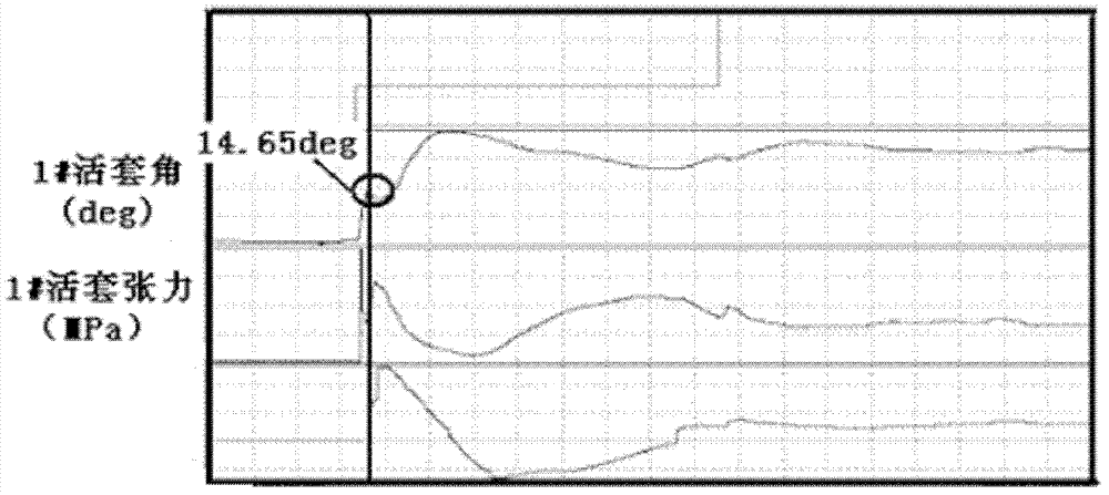
When the loop control is turned on, the loop angle is too small (14.65deg), and the loop tension is greater than the target value, resulting in abnormal loop control, which narrows the strip head until it breaks

Method used


Image

  • Forecasting method for loop length of hot continuous rolling mill
  • Forecasting method for loop length of hot continuous rolling mill
  • Forecasting method for loop length of hot continuous rolling mill

Examples


Embodiment Construction

[0031] Such as Figure 4 As shown, obtain the cover quantity coefficient of six loopers on the hot continuous rolling mill according to the following steps (in the present embodiment, the strip steel is ordinary carbon steel, and the thickness is 3.0mm):

[0032] (1) Determine the set amount LOOP1 of the six loops between the hot rolling mill stands at the moment of strip steel bite j , the calculation results are shown in Table 1:

[0033] LOOP 1 j = 1 2 · V 1 j · t j - - - ( 1 )

[0034] In formula (1), V 1j When the steel strip is bitten, the speed drop value of the hot rolling mill stand corresponding to the jth looper (when the strip steel bites, the speed of the stand is impacted,...


PUM


Abstract

The invention provides a forecasting method for loop length of a hot continuous rolling mill, which is used for forecasting all loop lengths between racks of hot continuous rolling before strip steel threading. According to the invention, the speed of anti-loop opening or anti-narrowing of the hot continuous rolling mill the loop corresponding to each loop can be obtained through the loop length generated at the moment of strip steel biting and speed drop compensation valve in order to prevent loop opening or loop narrowing, so as to obtain a loop length coefficient. The more is the loop length coefficient close to zero, the more stable threading of the strip steel can be realized, and accordingly, loop opening and narrowing can be avoided.

Description

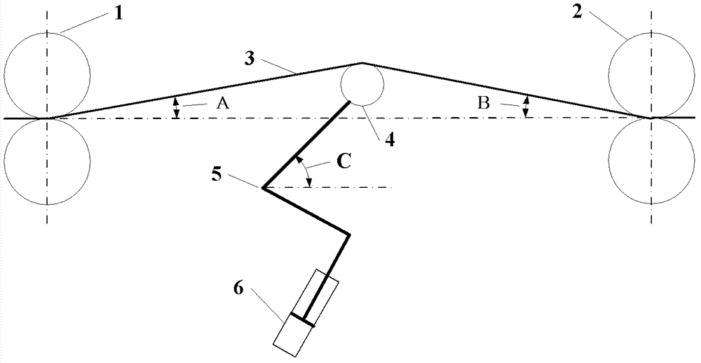
technical field [0001] The invention relates to a control method in a metallurgical process, in particular to a control method for a looper in a hot continuous rolling mill. Background technique [0002] Strip threading is a very important and difficult to control link in the hot rolling operation process. When threading the strip, the strip bites into the frame, causing a sudden change in the load of the rolling mill, which causes a dynamic speed drop in the transmission system. [0003] The looper system of hot continuous rolling uses the amount of loops formed by the dynamic speed drop to control looping. At present, the newly built production lines all use hydraulic loopers with high positioning accuracy and fast response speed, and their structural settings are as follows: figure 1 As shown, a looper roller 4 is arranged between the upstream frame 1 and the downstream frame 2, the looper angle is C, the front elevation angle is A, and the back elevation angle is B, an...

Claims


Application Information

Patent Timeline
Patent Type & Authority Applications(China)
IPC IPC(8): B21B41/00B21B37/50
Inventor 荣鸿伟谢捷何晓明
Owner BAOSHAN IRON & STEEL CO LTD
Why Eureka
Try Eureka