Robot joint driver with variable rigidity

A technology of robot joints and drives, applied in the directions of manipulators, manufacturing tools, joints, etc., can solve the problems of independent elastic links and adjustment mechanisms.

Active Publication Date: 2013-07-10
遨博(北京)智能科技股份有限公司
View PDF7 Cites 34 Cited by
  • Summary
  • Abstract
  • Description
  • Claims
  • Application Information

AI Technical Summary

Problems solved by technology

The main disadvantage of the existing variable stiffness joint driver

Method used


Image

  • Robot joint driver with variable rigidity
  • Robot joint driver with variable rigidity
  • Robot joint driver with variable rigidity

Examples


Embodiment Construction

[0014] Embodiments of the present invention are described below in conjunction with the accompanying drawings.

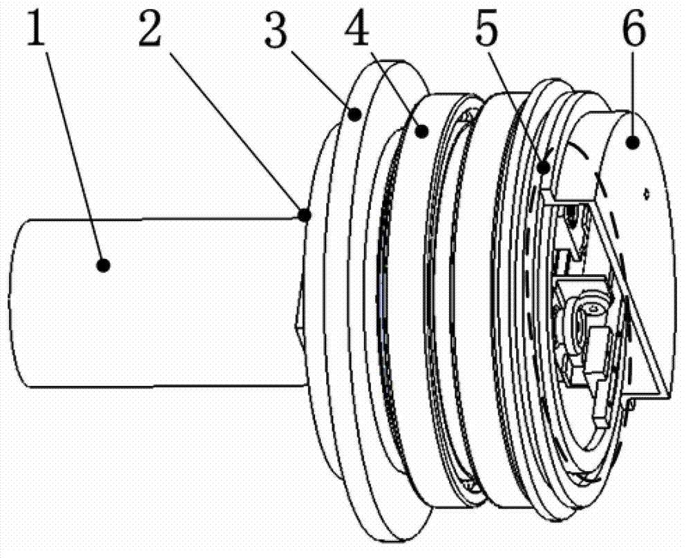
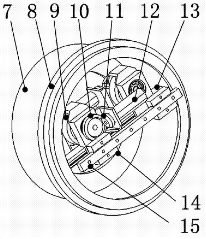
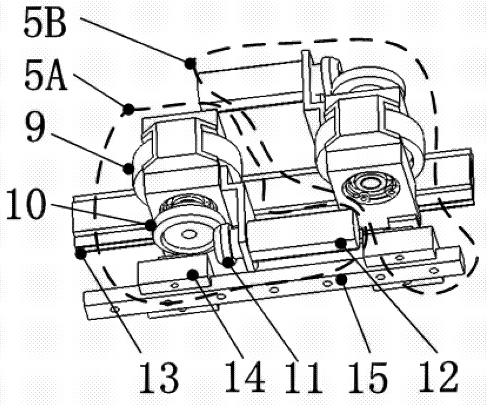
[0015] A typical feature of the variable stiffness robot joint driver is that the elastic link and the adjustment mechanism are combined into one by using a metal flexible rack mechanism. A metal flexible rack is connected in series between the output end of the rigid reducer of the joint driver and the shutdown link. The flexible rack itself has a certain degree of elasticity, which can effectively store and release energy, so as to avoid the rigid collision between the joint connecting rod and the environment; the flexible rack has its own gear pair, which is convenient for the adjustment of joint stiffness. Need to quickly increase or decrease joint stiffness.

[0016] In the process of man-machine collaborative operation, contact or even collision between humans and robots is inevitable. Therefore, how to ensure that the impact force does not harm the human bod...


PUM


Abstract

The invention provides a robot joint driver with variable rigidity and relates to joint rigidity adjustment by utilizing a flexible rack mechanism. The flexible rack mechanism is connected between the output end of a rigid speed reducer and a joint connecting rod in series. A pair of rigidity adjusting mechanisms is anti-symmetrically arranged along the axial direction of a flexible rack, and accordingly forward and reverse joints are adjustable. Displacement of a gear relative to the flexible rack is solely confirmed through a turn angle of a rigidity adjusting motor by utilizing the flexible rack mechanism, accordingly a joint rigidity value is confirmed solely, and joint rigidity adjustment can be achieved by controlling the turn angle of the rigidity adjusting motor. The robot joint driver adopts the flexible rack mechanism, integrates an elastic link and the rigidity adjusting mechanisms and is short in adjusting time and compact in structure.

Description

technical field [0001] The invention relates to a robot joint driver with variable stiffness, in particular to a robot joint driver with variable stiffness using metal flexible racks. The metal flexible rack plays the dual role of the elastic link and the joint stiffness adjustment mechanism in the joint driver. Background technique [0002] The most prominent problem in the current field of robotics is how to improve the adaptability of robots. Passive flexibility and active force control are two common methods used to improve robot adaptability. A typical case of passive flexibility is indirect central compliance RCC (Remote Center Compliance), but its flexibility is difficult to be actively controlled, and its application is narrow. Active force control requires an external high-precision force sensor; the accuracy of the sensor, the bandwidth of the sampling frequency, and the real-time performance of the control algorithm are extremely high; it is difficult to ensure ...

Claims


Application Information

Patent Timeline
IPC IPC(8): B25J17/00
Inventor 王伟王刚贠超
Owner 遨博(北京)智能科技股份有限公司
Why Eureka
Try Eureka