Concealed section beam-column connection structure

A concealed type, connection structure technology, applied in the direction of connection components, rod connection, building components, etc., can solve the problems of unsuitability and easy disassembly, and achieve the effect of good rigidity, stable and reliable connection, avoiding shaking and displacement

Active Publication Date: 2015-02-25
CHONGQING INTERL SCI & TECH COMM
View PDF6 Cites 0 Cited by
  • Summary
  • Abstract
  • Description
  • Claims
  • Application Information

AI Technical Summary

Problems solved by technology

But it is not suitable for the connection of beams and columns that are easy to disassemble and need to be built repeatedly

Method used


Image

  • Concealed section beam-column connection structure
  • Concealed section beam-column connection structure
  • Concealed section beam-column connection structure

Examples


Embodiment Construction

[0035] The present invention will be further described below in conjunction with the accompanying drawings and embodiments.

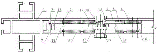
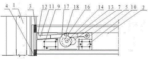
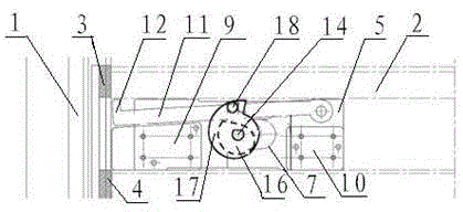
[0036] see figure 1 , Figure 5 to Figure 12 , a concealed profile beam-column connection structure, comprising a profile column 1 and a profile beam 2 vertically connected to the profile column. An upper block 3 and a lower block 4 are provided, and a telescopic connection locking mechanism is provided in the cavity of the profile beam body 2, and the connection locking mechanism extends into the T-shaped groove on one side of the profile column 1 The part cooperates with upper block 3 and lower block 4.

[0037] Further, the connection locking mechanism includes: a first slide plate 5 and a second slide plate 6, the contour dimensions of the first slide plate and the second slide plate are the same, and the width is slightly smaller than the height of the cavity of the profile beam body 2 and are parallel to each other. It is provided that the sam...


PUM


Abstract

A concealed connection structure for profiled beams and columns comprises a profiled column (1), and a profiled beam (2) perpendicularly connected to the profiled column (1). An upper plug (3) and a lower plug (4) are pre-arranged in a T-shaped groove on one side of the profiled column (1). A retractable connection-locking mechanism is arranged in a cavity of the profiled beam (2); said retractable connection-locking mechanism extends into the T-shaped groove on the side of the profiled column (1) and fits to the upper plug (3) and the lower plug (4). The connection structure allows convenient assembly and disassembly, and features high rigidity and stability at the joint.

Description

technical field [0001] The invention relates to a building frame structure, in particular to a concealed profile beam and column connection structure. Background technique [0002] The existing beam-column structure of aluminum alloy profiles that is easy to disassemble and needs to be built repeatedly, such as the second-floor exhibition structure of a temporary building, will shake in the horizontal direction due to poor rigidity of the beam-column joints, and even cause horizontal interference and cause instability Case. The main reason for the poor rigidity of the beam-column joints is that most temporary beam-column structures cannot be welded or riveted, and because of the need for open space or aesthetics, too many cross linings or oblique linings cannot be added, and T-shaped connectors are mostly used. to connect. The following problems exist in the use of T-type connectors: [0003] (1) A gap must be reserved at the beam-column connection, otherwise the screw ho...

Claims


Application Information

Patent Timeline
Patent Type & Authority Patents(China)
IPC IPC(8): E04B1/58E04B1/343
CPCE04B2/766F16B7/04E04B2/7809E04B2/7818F16B2/18F16B7/22
Inventor 刘西嘉
Owner CHONGQING INTERL SCI & TECH COMM
Why Eureka
Try Eureka