Bending type heat exchanger

A technology of heat exchanger and bending section, which is applied in the direction of heat exchanger shell, heat exchange equipment, evaporator/condenser, etc., can solve the problems of heat exchange performance impact, achieve good heat exchange effect, good drainage effect, The effect of improving the drainage effect

Active Publication Date: 2013-07-10
SANHUA HANGZHOU MICRO CHANNEL HEAT EXCHANGER
View PDF5 Cites 24 Cited by
  • Summary
  • Abstract
  • Description
  • Claims
  • Application Information

AI Technical Summary

Problems solved by technology

However, in some application environments, the heat tra

Method used


Image

  • Bending type heat exchanger
  • Bending type heat exchanger
  • Bending type heat exchanger

Examples


Embodiment Construction

[0038] Embodiments of the present invention are described in detail below, examples of which are shown in the drawings, wherein the same or similar reference numerals designate the same or similar elements or elements having the same or similar functions throughout. The embodiments described below by referring to the figures are exemplary only for explaining the present invention and should not be construed as limiting the present invention.

[0039] In describing the present invention, it should be understood that the terms "center", "longitudinal", "transverse", "upper", "lower", "front", "rear", "left", "right", " The orientations or positional relationships indicated by "vertical", "horizontal", "top", "bottom", "inner" and "outer" are based on the orientations or positional relationships shown in the drawings, and are only for the convenience of describing the present invention and Simplified descriptions, rather than indicating or implying that the device or element refe...


PUM


Abstract

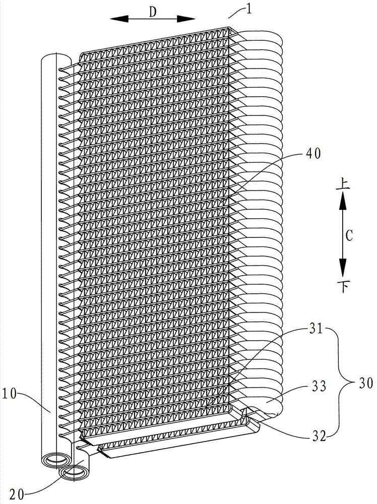
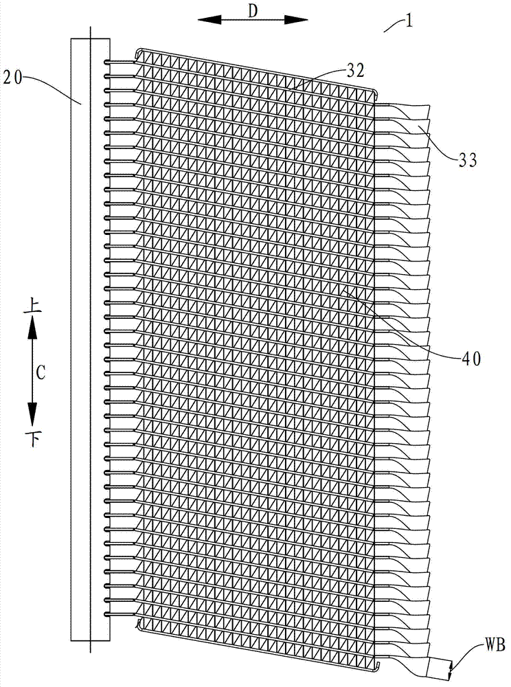
The invention discloses a bending type heat exchanger which comprises a first collecting pipe, a second collecting pipe, a plurality of flat pipes and corrugated fins, wherein two ends of each flat pipe are connected with the first collecting pipe and the second collecting pipe, each flat pipe comprises a first section, a second section and a bending section positioned between the first section and the second section, the bending section is twisted around the length direction of the flat pipe relative to the first section and the second section to form a predetermined torsion angle, the flat pipe is bent at the bending section to form a predetermined included angle between the first section and the second section, the first section and the second section are obliquely arranged relative to the horizontal direction, and the bending sections of the flat pipes are aligned in the vertical direction to form funnel vortexes; and the corrugated fins are arranged between the first sections of the adjacent flat pipes as well as between the second sections of the adjacent flat pipes respectively. The bending type heat exchanger provided by the embodiment of the invention is good in heat exchange effect and draining effect.

Description

technical field [0001] The invention relates to a heat exchanger, in particular to a bent heat exchanger used as an evaporator. Background technique [0002] When the existing parallel flow heat exchanger is used as a condenser, the flat tubes are placed horizontally, but when used as an evaporator, the flat tubes need to be placed vertically to enhance drainage performance. However, the heat transfer performance of this type of evaporator is affected in some application environments. Contents of the invention [0003] The present application is based on the inventor's recognition of the following problems and the fact that the application of the evaporator with flat tubes placed vertically is limited by the size of the heat exchanger, and the heat transfer performance is affected. For example, when the evaporator is required to have a large length and a small height, for example, the space for installing the evaporator is a rectangular space with a large horizontal dimen...

Claims


Application Information

Patent Timeline
IPC IPC(8): F25B39/02F28F9/26F28F17/00
Inventor 高强刘华钊
Owner SANHUA HANGZHOU MICRO CHANNEL HEAT EXCHANGER
Why Eureka
Try Eureka