Layered Synchronous Three-dimensional Particle Image Velocimetry Method and Device

A particle image velocimetry, three-dimensional technology, applied in measurement devices, fluid velocity measurement, velocity/acceleration/shock measurement, etc., can solve the problems of particle overlap, high cost, small size, and the maximum cannot exceed ten millimeters, and achieves high feasibility performance and reliability, high reliability of system hardware, and the effect of avoiding time delay

Inactive Publication Date: 2015-08-12
TIANJIN UNIV
View PDF4 Cites 2 Cited by
  • Summary
  • Abstract
  • Description
  • Claims
  • Application Information

AI Technical Summary

Problems solved by technology

The above-mentioned three-dimensional PIV technologies all have their own limitations. For example, the measurement section thickness of the volume perspective method is generally small, and the maximum cannot exceed more than ten millimeters, otherwise the overlapping and mismatching of particles will be very serious; the holographic image method is limited by the holographic technology. , the current cost is very high, and the corresponding algorithm is not mature enough, so it is difficult to be widely used; and the slice scanning method can obtain richer three-dimensional flow field data by using the existing two-dimensional PIV algorithm. However, due to the scanning time period, Different sections cannot be measured synchronously, and in fluid mechanics analysis, flow space correlation calculations strictly require simultaneous acquisition of flow velocity data at different measurement locations
In addition, the periodic scanning motion of the sheet light source complicates the mechanical design and the synchronous control with the camera, which brings difficulties to popularization and application.

Method used


Image

  • Layered Synchronous Three-dimensional Particle Image Velocimetry Method and Device
  • Layered Synchronous Three-dimensional Particle Image Velocimetry Method and Device
  • Layered Synchronous Three-dimensional Particle Image Velocimetry Method and Device

Examples


Embodiment Construction

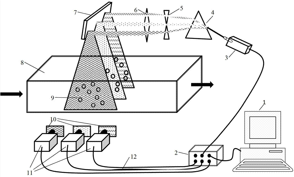
[0024] The layered synchronous three-dimensional particle image velocimetry (PIV) technology of the present invention uses a triangular prism beam splitting device to disperse the incident multi-color laser light into different color light sources and illuminate the test area at the same time; the illuminated particle images are in different sections Presents different color characteristics. Set up a group of CCD cameras near the test area, and each camera lens is equipped with a specific color filter, which is consistent with the color of the light source, so that the camera can only shoot sections of the corresponding color. All cameras work at the same time to obtain particle images on different sections simultaneously, and perform two-dimensional particle image analysis on each section, and perform correlation analysis on the images between different sections to obtain three-dimensional flow field information.

[0025] The present invention will be described in detail below w...


PUM


Abstract

The invention relates to the technical field of hydromechanics model tests, and provides a particle picture speed measuring technique which is efficient, reliable and strict and synchronous in measurement of different sections. According to a lamination synchronous three-dimensional particle picture speed measuring method, incident multi-color lasers are dispersed to light sources of different colors by a triple prism light splitting device, and meanwhile the light sources illuminate to a testing area; an illuminated particle picture presents different color characteristics in different sections; a set of charge coupled device (CCD) video cameras are arranged near the testing area, an optical filter in a certain color is added to the front of a lens of each video camera, the colors of the optical filters are matched with those of the light sources, so that the video camera can only shoot the section with the corresponding color; and all the video cameras work simultaneously, particle pictures on different sections are obtained simultaneously, two-dimensional particle picture analysis is conducted on each section, relative analysis is conducted on pictures among different sections, and three-dimensional flow field information is obtained. The method is mainly applied to testing and measuring of hydromechanics models.

Description

Technical field [0001] The invention relates to the technical field of fluid mechanics model testing, in particular to a flow field particle image flow velocity measurement technology, in particular to a layered synchronous three-dimensional particle image velocity measurement method. Background technique [0002] The measurement of flow field is an important technical means of fluid mechanics experiment, and it is very important in the research of aerodynamics and hydrodynamics. Particle Image Flow Velocity (PIV) is a fluid dynamics velocimetry method developed in the late 1970s. Its principle is to spread a large number of tracer particles in the flow field to follow the movement of the flow field, and use a laser to provide a light source to illuminate The flow field is cross-section, and a digital camera is used to take a picture of the flow field. Finally, the velocity distribution is obtained by cross-correlation calculation of the two or more frames of particle images. PI...

Claims


Application Information

Patent Timeline
Patent Type & Authority Patents(China)
IPC IPC(8): G01P5/22
Inventor 许栋白玉川徐海珏
Owner TIANJIN UNIV
Why Eureka
Try Eureka