Load fuse wire detecting device and power system

A detection device and fuse technology, applied in the directions of measuring devices, measuring electricity, circuit devices, etc., can solve the problems of poor compatibility of power supply systems and waste of energy, and achieve the effect of solving poor compatibility and waste of energy.

Active Publication Date: 2013-07-10
ANHUI DYNAMIC POWER
View PDF4 Cites 7 Cited by
  • Summary
  • Abstract
  • Description
  • Claims
  • Application Information

AI Technical Summary

Problems solved by technology

[0016] The object of the present invention is to provide a load fuse detection device and a power supply system, which can improve the compatibility of the load fuse detection device and improve the use efficiency of the power supply system by setting a state detection unit and an auxiliary power supply; Some technical problems such as poor compatibility of fuse detection devices and power supply systems and waste of energy

Method used


Image

  • Load fuse wire detecting device and power system
  • Load fuse wire detecting device and power system
  • Load fuse wire detecting device and power system

Examples


Embodiment Construction

[0047] The following descriptions of the various embodiments refer to the accompanying drawings to illustrate specific embodiments in which the present invention can be practiced. The directional terms mentioned in the present invention, such as "up", "down", "front", "back", "left", "right", "inside", "outside", "side", etc., are for reference only The orientation of the attached schema. Therefore, the directional terms used are used to illustrate and understand the present invention, but not to limit the present invention.

[0048]In the figures, structurally similar units are denoted by the same reference numerals.

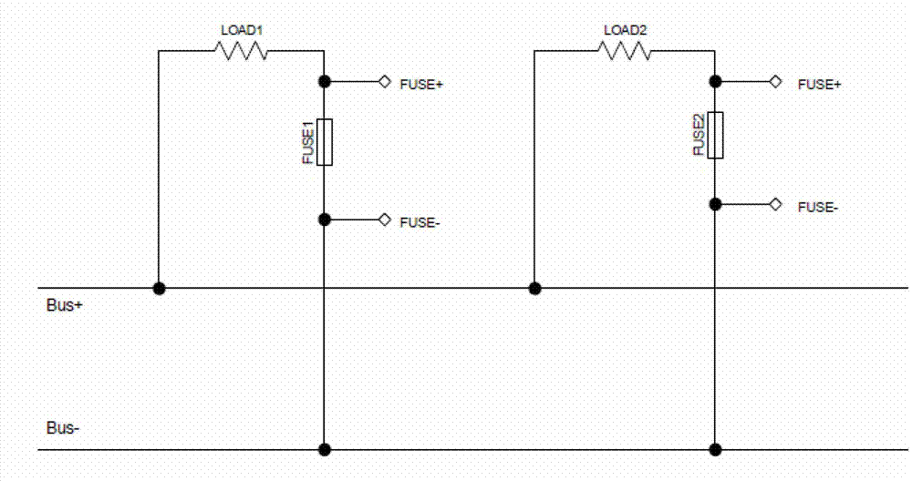
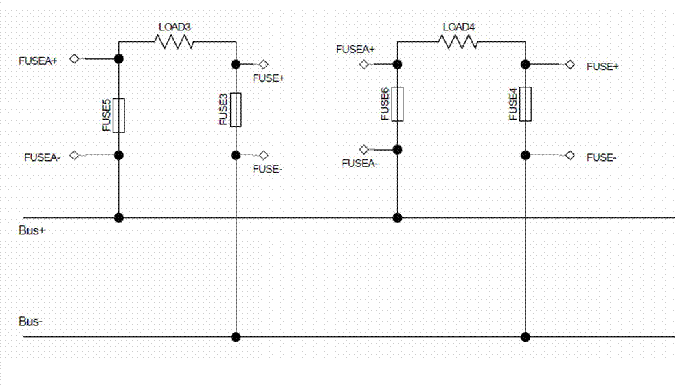
[0049] Please refer to image 3 , Figure 5 as well as Figure 6 , image 3 is a schematic structural diagram of an existing high-voltage power supply system, Figure 5 It is a schematic diagram of the structure of the load fuse detection device of the present invention when it is set between the negative pole of the load and the power supply, Figure 6 ...


PUM


Abstract

The invention relates to a load fuse wire detecting device and a power system. The load fuse wire detecting device comprises a fuse wire state detecting module and an alarming module. The fuse wire state detecting module comprises a state detecting unit and an auxiliary power supply, the state detecting unit is used for detecting whether a corresponding fuse wire is disconnected or not, and the auxiliary power supply is used for guaranteeing the state detecting unit to work normally when the corresponding fuse wire is not disconnected. The alarming module is used for sending alarming signals according to the detecting result of the state detecting unit. The invention further relates to the power system. The fuse wire detecting device and the power system enable the compatibility of the fuse wire detecting device to be strong and improve the using efficiency of the power system through the arrangement of the state detecting unit and the auxiliary power supply.

Description

technical field [0001] The invention relates to the field of circuit detection, in particular to a load fuse detection device and a power supply system with strong compatibility and energy saving. Background technique [0002] Existing power systems are provided with corresponding load fuses to protect the power system and corresponding loads. In a general power supply system, a load fuse is connected in series between the negative pole of the load and the power supply, and a load fuse detection device is also provided in the power supply system to detect the state of the load fuse. The structural diagram of this power supply system and load fuse detection device is as follows: figure 1 and figure 2 as shown, figure 1 is a schematic structural diagram of an existing power supply system, figure 2 It is a structural schematic diagram of the first embodiment of the existing load fuse detection device. Among them, Bus+ is the positive pole of the power supply, Bus- is the...

Claims


Application Information

Patent Timeline
IPC IPC(8): G01R31/02
CPCG01R31/74H02H3/046
Inventor 宋华
Owner ANHUI DYNAMIC POWER
Why Eureka
Try Eureka