Method and device used for automatically controlling state indicator lamp of terminal equipment

A technology of terminal equipment and indicator lights, which is applied to display devices, lighting devices, energy-saving control technologies, etc., can solve the problems of not achieving intelligent effects, and the bedroom environment interferes with users' rest, and achieves the effect of avoiding interruptions.

Inactive Publication Date: 2013-07-10
ZTE CORP
View PDF5 Cites 21 Cited by
  • Summary
  • Abstract
  • Description
  • Claims
  • Application Information

AI Technical Summary

Problems solved by technology

Control and display the more indicator lights of each functional module, the more power consumed per unit time. At the same time, this indicator light will always work as long as the functional module is running. For example, the user has a rest at night and the user has been driving the terminal device to download data. At this time, the long-term flashing of the status indicator will inevitably affect the bedroom environment and interfere with the user's rest.
[0003] At present, the patented technology related to the indicator light control of terminal equipment mainly provides a method of manually controlling the status indicator light through the switch. The switch is realized through hardware circuit switch control or software logic switch control, which has a lot to do with the user's operating habits. It has not yet achieved the real intelligent effect, but only provides users with a method to improve their subjective experience, and it is also limited to be used only in home gateways

Method used


Image

  • Method and device used for automatically controlling state indicator lamp of terminal equipment
  • Method and device used for automatically controlling state indicator lamp of terminal equipment
  • Method and device used for automatically controlling state indicator lamp of terminal equipment

Examples


Embodiment Construction

[0042] The method and device for automatic do-not-disturb of the status indicator of the terminal device according to the present invention will be described below with reference to the accompanying drawings.

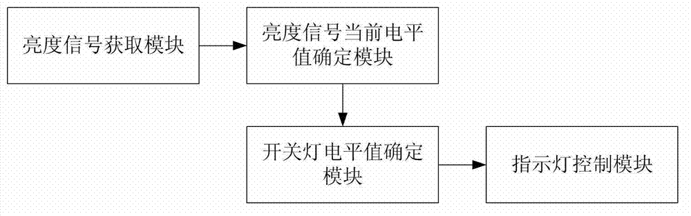
[0043] figure 1 The first embodiment of the device for automatically controlling the status indicator light of terminal equipment of the present invention is shown, as figure 1 Shown, the device of this embodiment comprises:

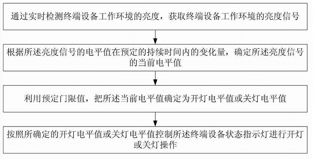
[0044] The brightness signal acquisition module is used to obtain the brightness signal of the working environment of the terminal equipment by detecting the brightness of the working environment of the terminal equipment in real time;

[0045] The current level value determination module of the brightness signal is used for determining the change amount of the level value(s) of the brightness signal within a predetermined duration (that is, the multiple level values ​​within the duration are relative to the reference voltage The amount of chang...


PUM


Abstract

The invention discloses a method and a device used for automatically controlling a state indicator lamp of terminal equipment. The method comprises the following steps: a brightness signal of the work environment of the terminal equipment is obtained by detecting the brightness of the work environment of the terminal equipment in real time; the current electric level value of the brightness signal is determined according to the variation amount of an electric level value of the brightness signal within a period of preset continuous time; the current electric level value is determined as a light-up electric level value or a light-off electric level value by utilizing a preset threshold value; and the state indicator lamp of the terminal equipment is controlled to carry out a light-up operation or a light-off operation according to the determined light-up electric level value or the light-off electric level value. The method and the device automatically control the light-up operation or the light-off operation of the state indicator lamp of the terminal equipment according to the brightness of the work environment of the terminal equipment, thereby avoiding the interference of the state indicator lamp on a user.

Description

technical field [0001] The present invention relates to the technical field of terminal communication, in particular to a method and device for automatically controlling a terminal status indicator light. Background technique [0002] With the development of network access technology, the application of home terminal equipment is becoming more and more popular, and the functional requirements are becoming more and more extensive. At the same time, there are more and more status indicators that control various functions, such as USB indicators, WAN indicators, DSL indicator light, LAN indicator light, VoIP indicator light, WLAN indicator light, power indicator light, etc. Control and display the more indicator lights of each functional module, the more power consumed per unit time. At the same time, this indicator light will always work as long as the functional module is running. For example, the user has a rest at night and the user has been driving the terminal device to d...

Claims


Application Information

Patent Timeline
Patent Type & Authority Applications(China)
IPC IPC(8): H05B37/02
CPCG09F13/005G09F27/005G09F13/0427Y02B20/40H05B47/11
Inventor 陈军成陈健杨利娜
Owner ZTE CORP
Why Eureka
Try Eureka