Sliding mechanism apparatus and appliance integrated with the same

a sliding mechanism and sliding mechanism technology, applied in the direction of electrical apparatus construction details, instruments, casings/cabinets/drawers, etc., can solve the problems of increasing the manufacturing cost of the sliding device, not having a means of providing a moving force, and prolonging the assembly time therefor. , to achieve the effect of smooth and stable sliding motion, reducing noise, and alleviating contact impa

Inactive Publication Date: 2007-04-26
LEE HAN SANG +1
View PDF7 Cites 52 Cited by
  • Summary
  • Abstract
  • Description
  • Claims
  • Application Information

AI Technical Summary

Benefits of technology

[0038] As described above, according to the invention, a cellular phone having a relatively small width W can achieve a desired maximum sliding distance L, thereby enabling to meet recent design requirements for cellular phones, pursuing a shorter, smaller and thinner type.
[0039] In addition, when the upper body of the cellular phone is tried to be pushed up to the uppermost state from the lowermost state, or vice versa, a user does not need to push up the upper body all the way up to the uppermost position or the lowermost position. That is, if the user pushed up or down the slider or guide member approximately halfway the maximum travel distance L, the slider or guide member can travel the remaining distance to thereby reach the uppermost or lowermost position, by means of the resilient force of the torsion spring. Thus, an operational convenience is provided when in use.
[0040] In particular, when sliding, the first and second guide bar and the first and second guide hole are mainly cooperated with each other to move relatively to each other, and the first and second guide dam and the first and second guide rail are also cooperated with each other so as not to be deviated or distorted from the horizontal movement thereof, thereby enabling a smooth and stable sliding motion of the slider and guide members.
[0041] Furthermore, the guide bar of the guide member and the guide hole of the slider member are provided with a bearing and a buffer rubber respectively, thereby alleviating contacting impact when sliding, and reducing noise therefrom.
[0042] In addition, a resilient contact plate is interposed between the slider member and the guide member so that the electrical contact therebetween can be maintained while sliding, thereby avoiding communication disorders, which may be caused by electromagnetic waves.
[0043] In the sliding mechanism apparatus of the invention, a pair of torsion springs is provided. The end portions of a variable arm are pivotably connected to both end of a variable link, which is provided in the slider member or the guide member. Thus, a dead point, which is likely to occur at a balancing area between elastic forces of the two torsion springs, can be minimized, thereby avoiding the halting phenomenon when sliding and thus extending the operational distance thereof. In addition, the variable arms of the torsion springs are bent outwardly at a certain angle such that the space required for pivot movement of the torsion springs can be minimized, thereby providing benefits in miniaturization therefor and reducing spring fatigue.

Problems solved by technology

However, the conventional sliding mechanisms do not have any means for providing a moving force for sliding, and thus the slider cover is made to move only as much as a user pushes up or down.
Thus, the sliding structure may be easily damaged by an external impact so that the cover can be released from the main body, thereby failing to provide a good durability.
Therefore, it leads to a complicated coupling structure, which will result in complicated molding dies, thereby consequently increasing the manufacturing cost of the sliding device and extending the assembling time therefor.
The above matters are considered as fundamental problems with the conventional sliding mechanisms.

Method used


Image

  • Sliding mechanism apparatus and appliance integrated with the same
  • Sliding mechanism apparatus and appliance integrated with the same
  • Sliding mechanism apparatus and appliance integrated with the same

Examples


first embodiment

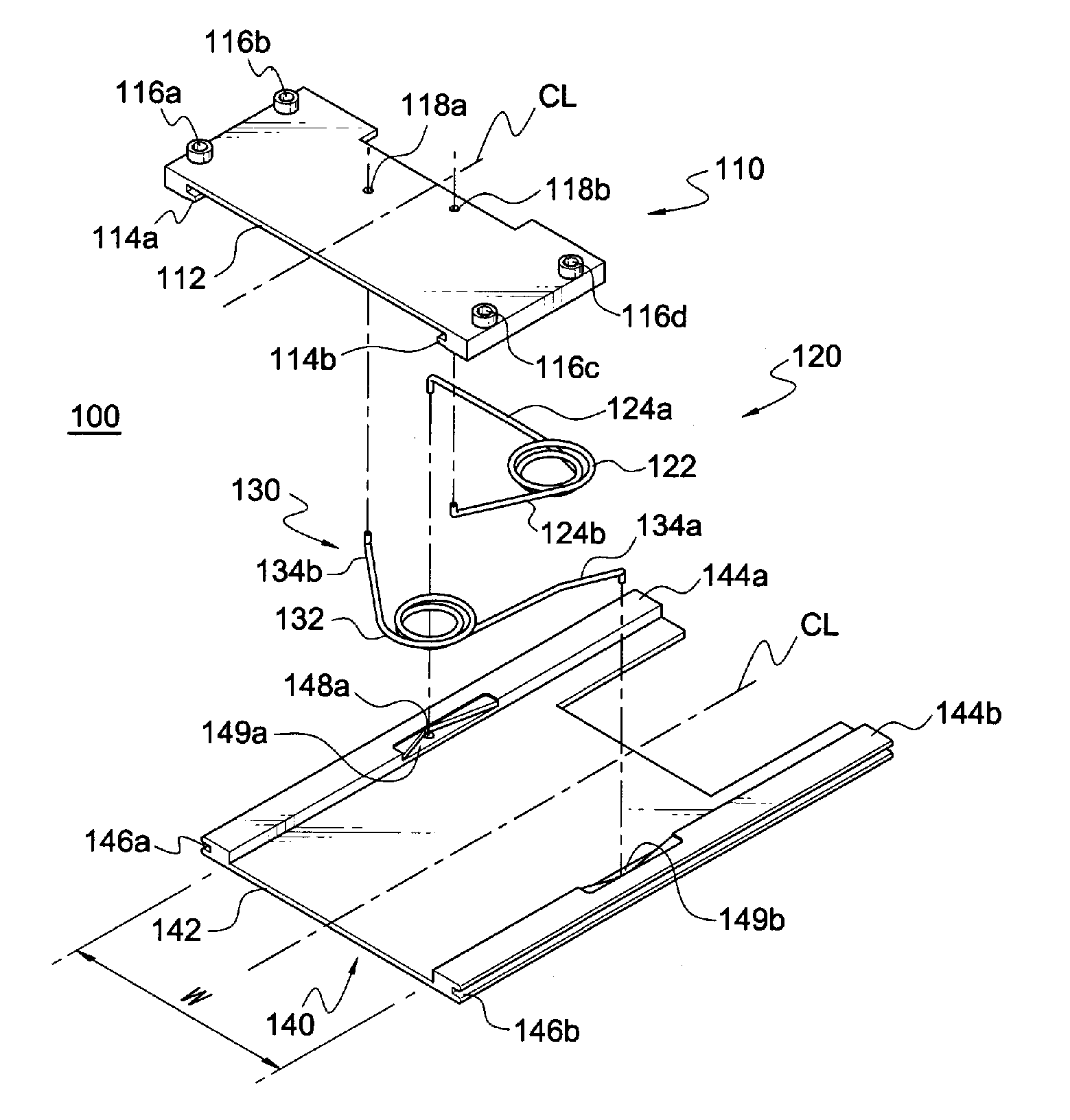
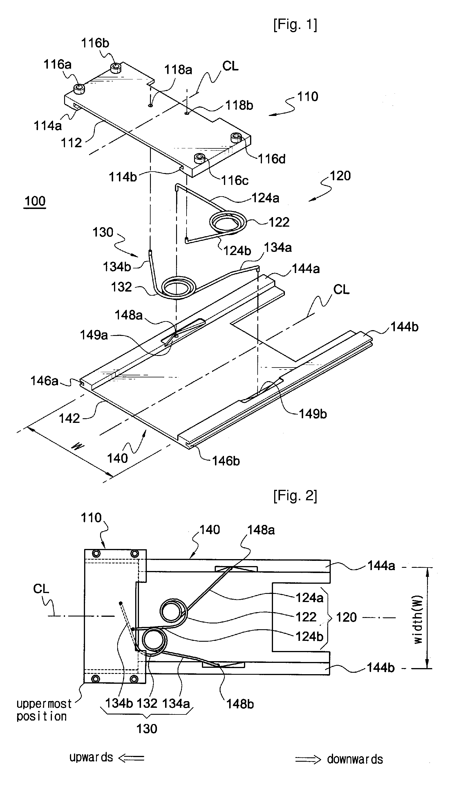
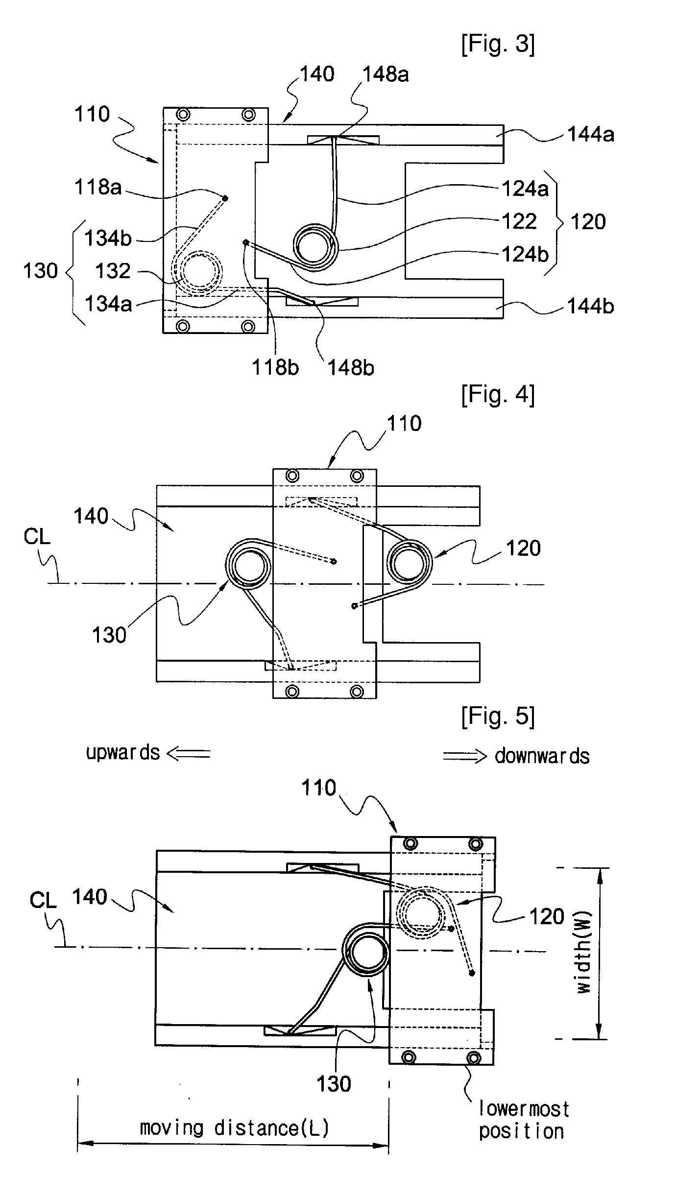
[0088]FIG. 1 is an exploded perspective view of a sliding mechanism apparatus according to the invention, where the sliding mechanism apparatus of the invention is denoted at 100. The sliding mechanism apparatus 100 of this embodiment includes a slider member 110, a first torsion spring 120, a second torsion spring 130, and a guide member 140.

[0089] The guide member 140 is comprised of a rectangular plate 142 and a first and second guide rails 144a and 144b elongated along both opposing parallel edges thereof. The first and second guide rails have a desired width and height respectively. In the outer face of the first guide rail 144a and the second guide rail 144b is formed respectively a first and second guide rail groove 146a, 146b in the longitudinal direction thereof. In addition, approximately in the middle of the first guide rail 144a is formed a V-shape groove 149a, and a connection hole 148a is formed at the apex of the V-shape groove 149a. Similarly, in the second guide rai...

fifth embodiment

[0129] On the other hand, the fifth embodiment as described above may be slightly modified into those constructions shown in FIGS. 22 and 23.

[0130]FIGS. 22 and 23 are respectively an exploded perspective view and an assembled cross-section of a sliding mechanism apparatus according to a sixth embodiment of the invention. As illustrated in FIGS. 22 and 23, a first and second slide-coupling hand 624a, 624b, which is provided in both sides of a rectangular base plate 622 in a slider member 620, is formed so as to be shorter than the length of the rectangular base plate 622, not over the entire length thereof. Thus, when in the uppermost or lowermost position, the rectangular base plate 622 of the slider member 620 can run beyond an upper and lower finishing crossbar 614, 618, thus extending the sliding distance of a slider-type cellular phone. That is, if the rectangular base plate 622 of the slider member 620 and the guide bar 650a, 650b of the guide member 610 have the same length as...

eighth embodiment

[0134]FIG. 28 is an assembled perspective view of a sliding mechanism apparatus 800 according to the invention, and FIG. 29 is a cross-section taken along the line F-F in FIG. 28. In this embodiment, the guide dam and guide rail structures are removed, and the relative sliding of a guide member 810 and a slider member 820 is guided through the engaging structure of guide bars 850a, 850b and guide holes 826a, 826b. In this sliding and guiding structure, the stability therefor is slightly inferior to the previous embodiments, but the slider member can be slid and guided without any hitch.


PUM


Abstract

Disclosed is a sliding mechanism apparatus used for slidably opening and closing a slider-type cellular phone. A guide member and a slider member are engaged with each other so as to enable to slide relative to each other. The end of one arm of a first torsion spring is connected to the slider member near the left edge thereof. The end of the other arm thereof is coupled to the right half area of the guide member. The end of one arm of a second torsion spring is connected to the slider member near the right edge thereof. The end of the other arm thereof is coupled to the left half area of the guide member. From the expanded original state of the first and second torsion springs, if an external force is exerted on the slider member or the guide member, the torsion springs are compressed into an acute angle and then spread again by means of the elastic force thereof. In this way, the slider member can move to the lowermost position or the lowermost position. In the first and second torsion springs, the distance between the ends of two arms is larger than at least half of the width of the slider member. Therefore, the first and second torsion springs can maximally utilize the width of the guide member while turning, thereby extending the maximum travel distance of the slider member.

Description

TECHNICAL FIELD [0001] The present invention relates to a sliding mechanism apparatus and an appliance thereof. More specifically, the invention relates to a sliding mechanism apparatus applicable to various slider-type devices such as a wireless communication terminal, in which the resilient force of a torsion spring is utilized to thereby improve the operational convenience thereof, and an appliance using such a sliding mechanism apparatus. BACKGROUND ART [0002] Portable communication terminals such as a cellular phone have been changing its external form or shape. For example, a flip-type, a bar-type, and a folder-type cellular phone have been known. Recently, a slider-type cellular phone has been commercialized and attracted attentions. In general, a slider-type portable terminal is comprised of a main body and a cover slidably engaged with the main body. That is, the cover opens and closes the main body while sliding upwards and downwards along the main body. [0003] Regarding t...

Claims


Application Information

Patent Timeline
Patent Type & Authority Applications(United States)
IPC IPC(8): G06F1/16H04B1/38H04M1/02
CPCH04B1/3833H04M1/0237
Inventor LEE, HAN SANG
Owner LEE HAN SANG
Why Eureka
Try Eureka