Tension clamps for rail fastening and systems equipped with such tension clamps
What is AI technical title?
AI technical title is built by PatSnap AI team. It summarizes the technical point description of the patent document.
A tension and track technology, applied in the field of tension clips, can solve problems such as application, and achieve the effects of loss avoidance, friction loss reduction, and risk reduction
Active Publication Date: 2016-06-01
VOSSLOH WERKE GMBH
View PDF9 Cites 0 Cited by
Summary
Abstract
Description
Claims
Application Information
AI Technical Summary
This helps you quickly interpret patents by identifying the three key elements:
Problems solved by technology
Method used
Benefits of technology
Problems solved by technology
However, it is difficult to apply a high spring force to the rail foot within the limited installation space and the correspondingly limited spring compression during this forming
Method used
Image
Click on the blue label to locate the original text in one second.
Reading with bidirectional positioning of images and text.
Examples
Embodiment Construction
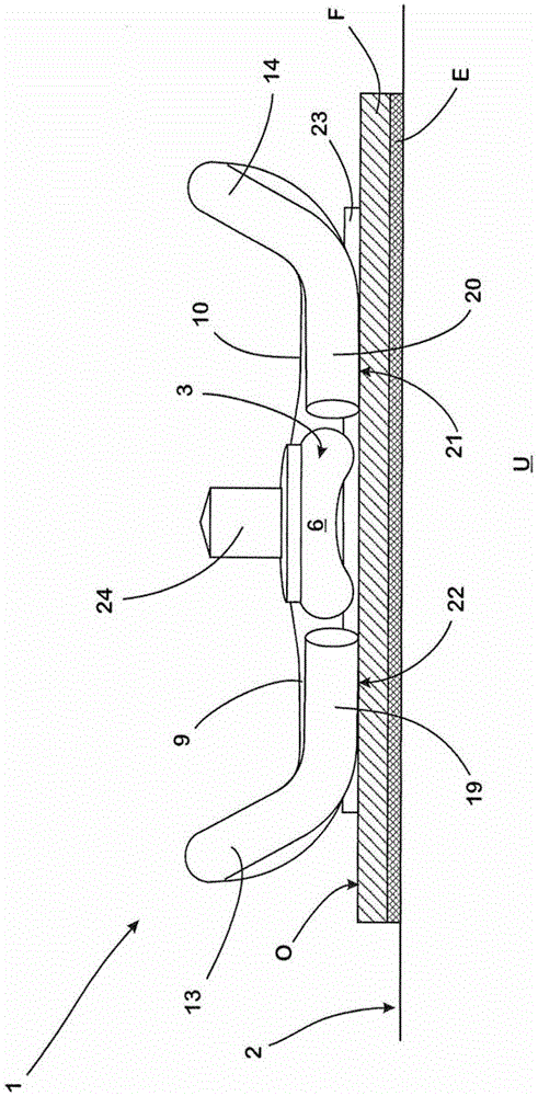
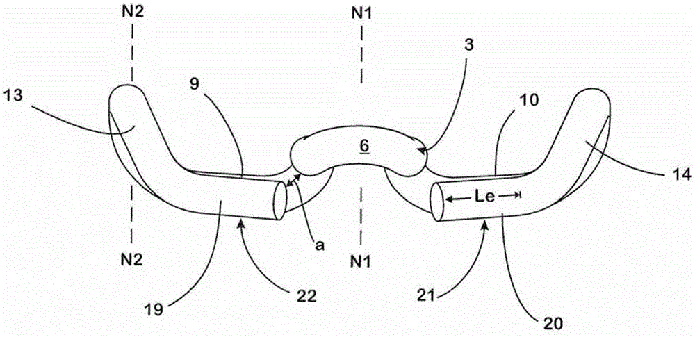
[0072] Tension clamps 1 , 50 for fixing the rail S supported on the base U (here formed from concrete sleepers), formed in one piece from spring steel wires in a curve without dead bends 1 , 50 with respect to the support to the base U The layer N1 perpendicular to the plane 2 is mirror-symmetrical. The tension clips respectively have ring-shaped, in plan view ( Figure 4 ) is a U-shaped middle section 3, which has two parallel and spaced apart arms 4, 5 and a rail foot corresponding to the track S to be fixed, connecting the two arms 4, 5 to each other The semicircular connection section 6 of F.
[0073] A laterally protruding torsion section 9 , 10 is connected to each arm 4 , 5 of the central section 3 via a first transition section 7 , 8 bent at 90°. The torsion sections 9 , 10 point in the opposite direction to the middle section 3 and form an angle α of approximately 90° with the legs 4 , 5 of the respective associated middle section in plan view.
[0074] Another sec...
PUM
Abstract
A tension clamp (1) for fastening a rail (S), having a central portion (3), having at least one torsion portion (9, 10) which extends in the lateral direction from the central portion (3), having at least one transition portion (7, 8) which adjoins the torsion portion (9, 10), and having at least one holding arm (13, 14) which is connected to the transition portion (7, 8) and of which the end portion (19, 20), which is assigned to the free end of the holding arm (13, 14), is aligned in an angled manner in relation to the torsion portion (9, 10) as seen in a plan view of the tension clamp (1), wherein, on the angled end portion (19, 20) of the holding arm (13, 14), there is formed a support region (21, 22) which extends over the length of the end portion (19, 20), and the end portion (19, 20) is angled in relation to a part (15, 16), which adjoins said end portion, of the holding arm (13, 14) such that, when the tension clamp (1) is in the fully installed state, the support region (21, 22) is supported over its entire length (Le) in a linear manner on the associated surface (O) of the rail foot (F) of the rail (S) to be fastened.
Description
technical field [0001] The invention relates to a tension clamp for rail fixing, the tension clamp has: a middle section; at least one torsion section branching from the middle section to the side; at least one transition section connected to the torsion section As well as at least one clamping arm connected to the transition section, the end section of the clamping arm corresponding to the free end of the clamping arm, viewed from a top view of the tensioning clamp, is bent in the opposite direction of the torsion section. Tension clamps of this type are usually bent in one piece from spring steel. [0002] The invention also relates to a system for fixing a rail having a rail foot, a web on the rail foot and a rail head, the system having a guide plate, a tension clip fixed on the guide plate and a Clamps for base clamp tension clamps. Background technique [0003] Such tension clips and systems are known from DE 10 2007 046 543 A1. In the known system, a tension clip i...
Claims
Application Information
Patent Timeline
Application Date:The date an application was filed.
Publication Date:The date a patent or application was officially published.
First Publication Date:The earliest publication date of a patent with the same application number.
Issue Date:Publication date of the patent grant document.
PCT Entry Date:The Entry date of PCT National Phase.
Estimated Expiry Date:The statutory expiry date of a patent right according to the Patent Law, and it is the longest term of protection that the patent right can achieve without the termination of the patent right due to other reasons(Term extension factor has been taken into account ).
Invalid Date:Actual expiry date is based on effective date or publication date of legal transaction data of invalid patent.

