
Methods of Attaching and Dismounting Using Temporary Suspension Elements

A component, suspension technology, applied in fixtures, metal processing equipment, metal processing, etc., can solve the problems of operator danger, tilt or fall, bulky, etc., to achieve the effect of low price, increase time or cost

Active Publication Date: 2015-11-25
ESSILOR INT CIE GEN DOPTIQUE
View PDF3 Cites 0 Cited by
  • Summary
  • Abstract
  • Description
  • Claims
  • Application Information

AI Technical Summary

Problems solved by technology

[0003] Additionally, the structure to be suspended may be heavy or bulky
Hazard to operators making connections if structure accidentally tilts or falls

Method used


Image

  • Methods of Attaching and Dismounting Using Temporary Suspension Elements
  • Methods of Attaching and Dismounting Using Temporary Suspension Elements
  • Methods of Attaching and Dismounting Using Temporary Suspension Elements

Examples


Embodiment Construction

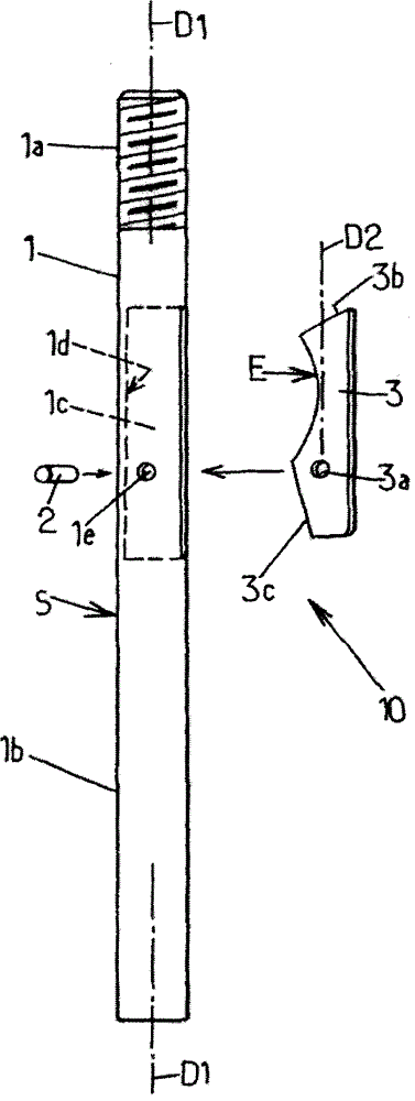
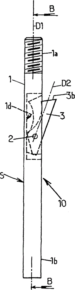
[0045] exist figure 1 Among them, the temporary suspension element 10 includes a linear guide 1 , a cross pin 2 and a hook 3 .

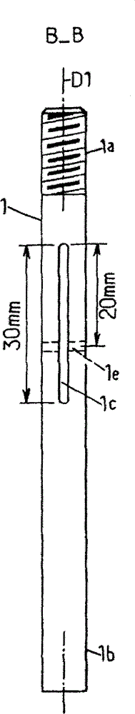
[0046] The linear guide 1 comprises a threaded end 1a and a cavity 1c at a distance from the thread of the end 1a. from Figure 2b As can be seen in , the cavity 1 c may be shaped as a slot within the width of the guide 1 . D1 denotes the longitudinal direction of the linear guide 1 . The outer surface S of the guide 1 is smooth and parallel to the direction D1 so as to form a sliding surface apart from the threaded end 1a and the cavity 1c. The guiding device 1 can be made of a cylindrical rod, such as a metal rod.

[0047]Optionally, the linear guide 1 can have a clamping end 1b opposite to the end 1a in the direction D1, the length of the end 1b from the cross pin 2 being greater than 50 mm (millimeters). The clamping end 1b can be round or conical in order to facilitate its introduction into the hole of the outer structure.

[0048] As an e...


PUM

PropertyMeasurementUnit
Lengthaaaaaaaaaa

Abstract

A temporary suspension element comprises a rectilinear guide with a threaded end, and a catch which can swing between a guiding position and a retaining position. The element can temporarily replace screws that attach a structure under a support, during the attachment or disassembly of said structure. The attachment and the disassembly of the structure can then be performed by a single operator.

Description

technical field [0001] The invention relates to methods of attachment and detachment using temporary suspension elements. Background technique [0002] It is not uncommon to suspend the structure from the support using attachment mechanisms such as screws, leaving the structure permanently under the support. However, such attachment mechanisms require manipulation and tools to install. During installation, the structure must be held in place by other means until the permanent attachment mechanism is finally installed and independently holds the structure in suspension. Most commonly, the first operator holds the structure in place during the connection while the second operator installs the connection mechanism. Therefore, two operators are required at the same time, which causes problems in repetitive connection operations. Such joining operations occur in industrial production processes that are repeated with each new manufacturing cycle. Therefore, it is important to ...

Claims


Application Information

Patent Timeline
IPC IPC(8): F16B1/00
CPCF16M13/027F16B1/00Y10T29/49815Y10T29/49963Y10T29/49947Y10T29/49895B23P19/04
Inventor 伊维斯·埃久伊博内乔斯·阿尔布夸奎丹尼尔·达梅斯
Owner ESSILOR INT CIE GEN DOPTIQUE
Features
  • Generate Ideas
  • Intellectual Property
  • Life Sciences
  • Materials
  • Tech Scout
  • Unparalleled Data Quality
  • Higher Quality Content
  • 60% Fewer Hallucinations
Learn More