Planetary gear reducer

A technology of gear reducer and planetary gear, which is applied in the direction of gear transmission, belt/chain/gear, mechanical equipment, etc., can solve the problem of increased manufacturing cost of components

Inactive Publication Date: 2013-07-10
JTEKT CORP
View PDF8 Cites 4 Cited by
  • Summary
  • Abstract
  • Description
  • Claims
  • Application Information

AI Technical Summary

Problems solved by technology

[0003] However, in order to integrally form the carrier and the pin, when the ...

Method used


Image

  • Planetary gear reducer
  • Planetary gear reducer
  • Planetary gear reducer

Examples


Embodiment Construction

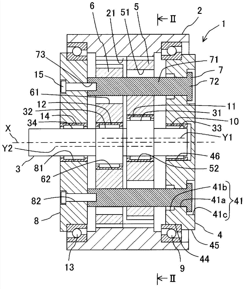
[0031] refer to figure 1 and figure 2 The planetary gear reducer 1 of this embodiment will be described. The planetary speed reducer 1 of the present embodiment is configured such that the eccentric cam portions 31 and 32 of the crankshaft 3 are configured as eccentric portions, and includes planetary gears as external gears rotatably supported by the eccentric cam portions 31 and 32 , respectively. 5, 6 these two gears, and the two planetary gears 5, 6 are configured to be clamped by the first side plate 4 and the second side plate 8 as the planetary gear carrier.

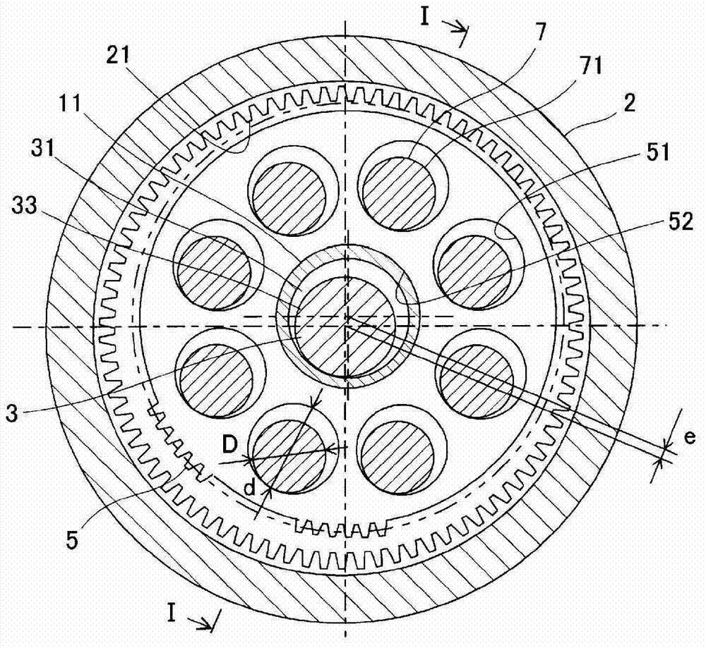
[0032]Specifically, the planetary gear reducer 1 is configured as follows. This planetary gear reducer 1 mainly includes a housing 2 , a crankshaft 3 , a first side plate 4 as a carrier, a second side plate 8 , a first planetary gear 5 , a second planetary gear 6 , and a plurality of pins 7 . The housing 2 is formed in a cylindrical shape, and an internal gear 21 is formed on the inner peripheral surface of th...


PUM


Abstract

Provided is a planetary gear reducer capable of being manufactured at low cost without integrally forming the carrier and pins. A first side plate (4), which is a carrier, has a circular disc-like shape, and pins (7) are affixed so as to protrude from one end surface of the first side plate (4) in the axial direction. The first side plate (4) has a small outer diameter on the one end surface side in the axial direction and a large outer diameter on the other end surface side in the axial direction. The first side plate (4) is provided with: press-fit hole sections (41a) into which the pins (7) are press fitted; and small-diameter-side recesses (41b) which are formed in the press-fit hole sections (41a) on the one end surface side in the axial direction, are open in the one end surface of the first side plate (4) in the axial direction, and each have, in at least a part thereof, an inner peripheral surface not in contact with the pin (7).

Description

technical field [0001] The present invention relates to a planetary gear reducer, the revolution center of the planetary gear of the planetary gear reducer is located inside the planetary gear. Background technique [0002] Japanese Patent Application Laid-Open No. 2006-263878 describes the following mechanism: In a planetary gear reducer in which the revolution center of the planetary gear is located inside the planetary gear, in order to transmit only the rotation motion of the planetary gear to the planetary carrier, the planetary gear A plurality of engaging holes are formed, and pins inserted through these engaging holes are formed integrally with the carrier. [0003] However, in order to integrally form the carrier and the pin, manufacturing the part of the pin by cutting will increase the manufacturing cost of the part. Contents of the invention [0004] The present invention has been made in view of such circumstances, and an object of the present invention is to...

Claims


Application Information

Patent Timeline
IPC IPC(8): F16H1/32
CPCF16H2001/325F16H1/32
Inventor 加藤喜绅太田浩充
Owner JTEKT CORP
Why Eureka
Try Eureka