Head gimbal assembly and disk drive unit with microactuator

A micro-actuator and magnetic head technology, applied in the direction of maintaining the alignment of the head frame, the configuration/installation of the recording head, etc., can solve the problems of affecting the dynamic performance of the magnetic head 103', affecting the performance of the magnetic head 103', and difficult to control the static pitch angle. Achieve the effects of reducing track-seeking time and positioning time, improving track-seeking ability, and improving track-reading accuracy

Active Publication Date: 2017-03-15
SAE MAGNETICS (HK) LTD
View PDF6 Cites 0 Cited by
  • Summary
  • Abstract
  • Description
  • Claims
  • Application Information

AI Technical Summary

Problems solved by technology

[0008] However, the above-mentioned cantilever tongue 131 of the HGA has an integrated structure, part of the cantilever wire 122 is arranged under the magnetic head 103', and the piezoelectric element 110' partly extends to the cantilever tongue 131 and is located under the magnetic head 103'. There is an overlapping intersection area between the element 110' and the magnetic head 103'. That is, a part of the magnetic head 103' is directly carried on the piezoelectric element 110'. On the other hand, under the impact of external force, it is difficult for the cantilever tongue to control the static pitch angle of the magnetic head 103', thereby affecting the dynamic performance of the magnetic head 103', and even causing the magnetic head 103' to break away from the bump 125 potential danger
And then also directly affect the performance of the magnetic head 103'

Method used


Image

  • Head gimbal assembly and disk drive unit with microactuator
  • Head gimbal assembly and disk drive unit with microactuator
  • Head gimbal assembly and disk drive unit with microactuator

Examples


Embodiment Construction

[0035] Several different preferred embodiments of the present invention will now be described with reference to the accompanying drawings, wherein like reference numerals in different drawings represent like parts. As mentioned above, the essence of the present invention is to provide a magnetic head gimbal assembly. The piezoelectric element on the cantilever can well control the rotation of the magnetic head on the cantilever tongue, and it is impact-proof and shock-proof, so that the static pitch of the magnetic head can be well controlled. Angle and rotation angle, and can precisely control the position of the magnetic head to control the ability of the magnetic head to track and maintain the track, and then adjust the accuracy of the magnetic head to read the track, improve the track density TPI value of the disk, and finally increase the capacity of the disk.

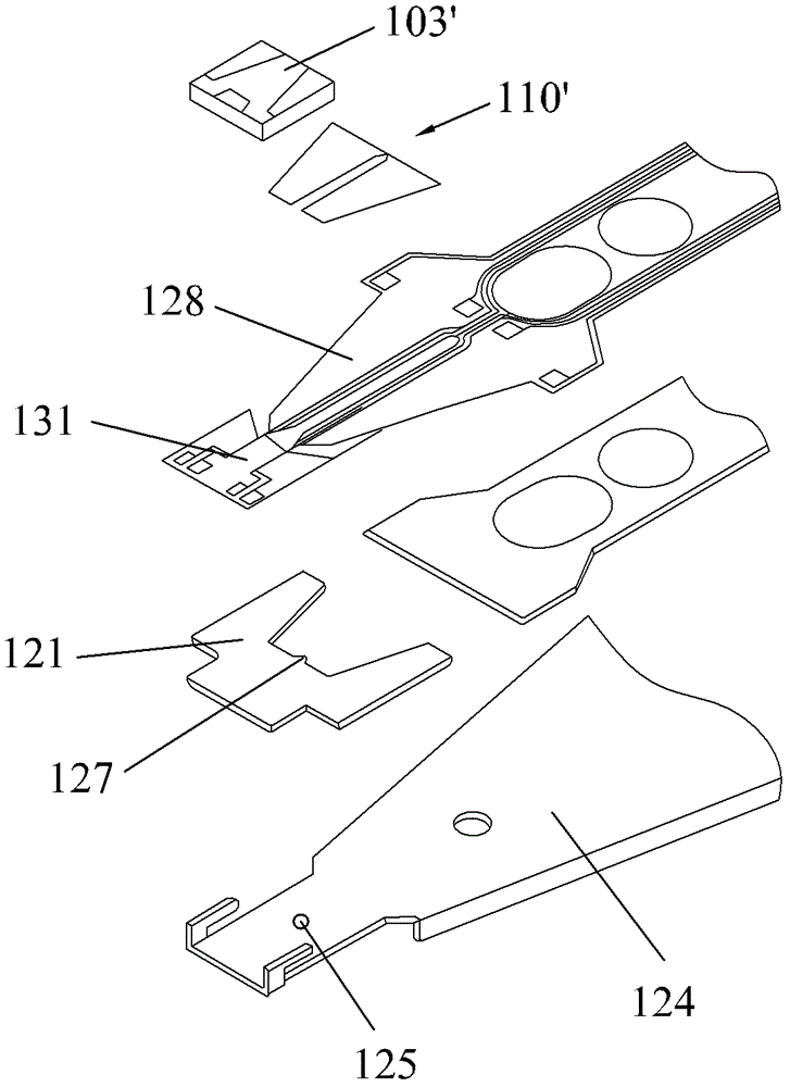
[0036] image 3 -5 shows the structural diagram of an embodiment of the HGA of the present invention. The HGA ...


PUM

PropertyMeasurementUnit
thicknessaaaaaaaaaa
thicknessaaaaaaaaaa

Abstract

The invention discloses a magnetic head gimbal assembly. A flexible member on the magnetic gimbal assembly comprises a thin rod connected with a cantilever tongue piece, an installation area for installing a piezoelectric element and a connection part connected with the thin rod and the installation area, wherein a support rod is arranged on the outer side of the installation area, one end of the support rod is connected with the thin rod through the connection part, and the other end of the support rod is connected with the installation area. A first gap is formed between the thin rod and the cantilever tongue piece, a second gap is formed between the support rod and the installation area, and a cantilever guide line is covered on the thin rod and the support rod. When the piezoelectric element on the installation area is driven, the connection part deforms along with the piezoelectric element on the installation area, so that the thin rod drives a magnetic head on the cantilever tongue piece to rotate around a universal joint. The magnetic head gimbal assembly is stable in structure, and strong in impact resisting performance, can well control a static pitch angle and a rotating angle of the magnetic head, can accurately control the position of the magnetic head on a disk so as to control the rail-finding and on-rail maintaining capability of the magnetic head, further adjusts the rail-reading accuracy of the magnetic head, and improves the true performance initiative (TPI) values and the capacity of the disk.

Description

technical field [0001] The present invention relates to an information recording disk drive unit, in particular to a head gimbal assembly (HGA) with a micro-actuator and the disk drive unit. Background technique [0002] A hard disk drive consisting of multiple spinning platters is commonly used to store data on magnetic media on its platter surfaces, with removable read / write transducers used to read data from or write data to the magnetic tracks on the platter surfaces . [0003] As consumers continue to pursue greater storage capacity of such disk drives, while demanding faster and more accurate read and write operations, many methods are used to improve the recording density of disk drives. However, as the track density increases, it becomes more and more difficult to quickly and accurately locate and track the read / write sensor on the information track of the magnetic disk. Therefore, disk drive equipment manufacturers are constantly looking for ways to improve the po...

Claims


Application Information

Patent Timeline
Patent Type & Authority Patents(China)
IPC IPC(8): G11B5/48G11B5/58
Inventor 姚明高山野井康友
Owner SAE MAGNETICS (HK) LTD
Why Eureka
Try Eureka