Antenna calibration method and base band unit

A technology for antenna calibration and channel calibration, applied in baseband system components, diversity/multi-antenna systems, space transmit diversity and other directions, it can solve the problem of high peak average, the signal no longer has the low peak-to-average ratio characteristic of ZC sequence, and unpredictable, etc. question

Active Publication Date: 2013-07-17
DATANG MOBILE COMM EQUIP CO LTD
View PDF3 Cites 12 Cited by
  • Summary
  • Abstract
  • Description
  • Claims
  • Application Information

AI Technical Summary

Problems solved by technology

However, due to the difference in the amplitude and phase of each sending channel, the coupled signal no longer has the low peak-to-average ratio characteristic of the ZC sequence, and the randomness of the phase difference will also make the peak-to-average ratio random, and the maximum peak-to-av

Method used


Image

  • Antenna calibration method and base band unit
  • Antenna calibration method and base band unit
  • Antenna calibration method and base band unit

Examples


Embodiment 1

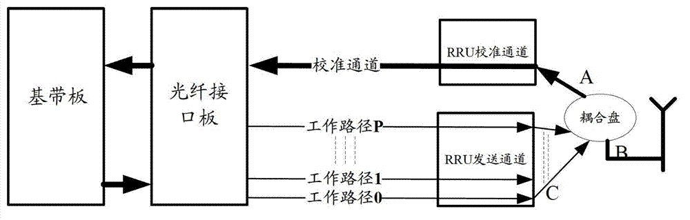
[0048] The specific process is as Figure 5A Shown:

[0049] Step 1: The BBU generates the calibration signal txCalSeq to be sent.

[0050] Step 2: Determine whether this calibration process is the first calibration process, if so, go to step 3, otherwise, go to step 4;

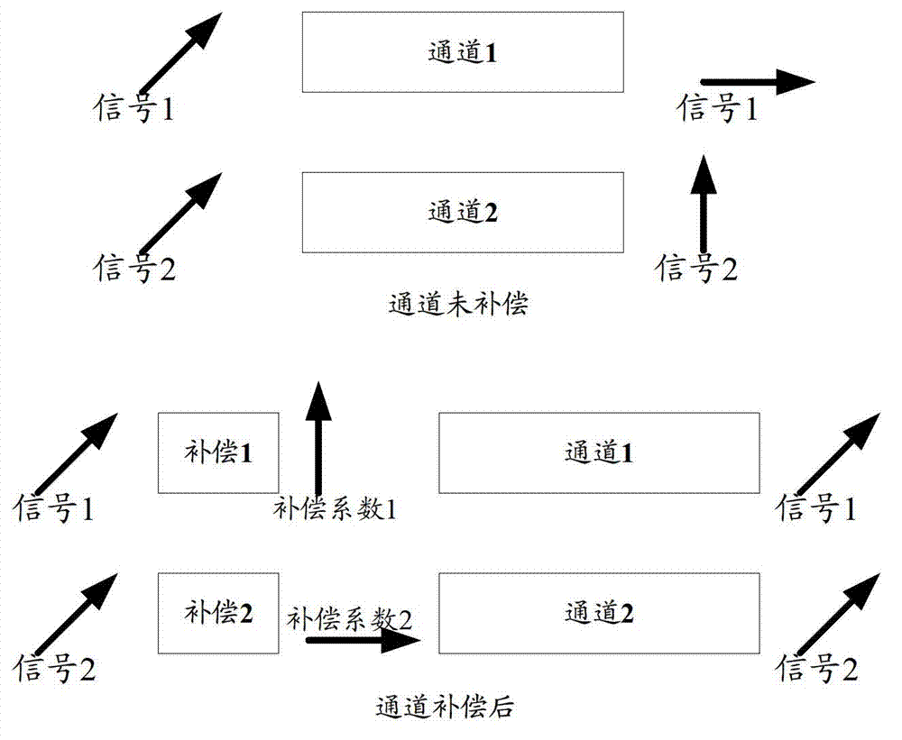
[0051] Step 3: Perform channel difference compensation on the calibration signal according to the phase compensation coefficient, that is, multiply the calibration signal by the phase compensation coefficient: txCalSeq_equalize=txCalSeq.PhaseCoeff, the phase compensation coefficient PhaseCoeff=1 or PhaseCoeff is the phase compensation coefficient obtained in the previous calibration cycle , and go to step 5;

[0052] Step 4: Perform channel difference compensation on the calibration signal according to the phase compensation coefficient, that is, multiply the calibration signal by the phase compensation coefficient, which is the phase compensation coefficient obtained in the previous calibration process;

...

Embodiment 2

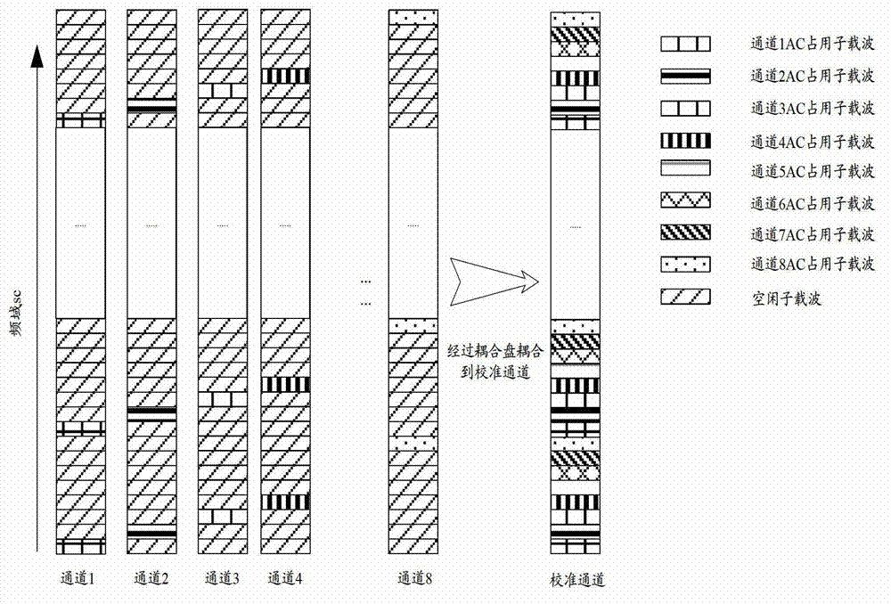
[0075] For an 8-channel, 20MHz bandwidth TD-LTE system, such as Figure 5B As shown, the example of the scheme is as follows:

[0076] Step 1: Generate ZC sequence according to system bandwidth. When the system bandwidth is 20MHz, the ZC sequence selects 1200 points. Then distribute 1200 points of ZC to 8 sending channels, the specific implementation is as follows:

[0077] L=1200; %1200 point sequence length

[0078] N_ZC=max(primes(L));% Find the largest prime number

[0079] m_zc=1193;%sequence index

[0080] Xk _ ZC = exp ( - li * p * m _ zc * ( 0 : ( L - 1 ...


PUM


Abstract

An embodiment of the invention discloses an antenna calibration method and a base band unit, belongs to the field of wireless communication and is used for improving the accuracy of antenna calibration. According to the scheme of the antenna calibration method and the base band unit, at least two times of calibration processes are performed in a current calibrating period after a calibrating signal to be sent is generated, and during every calibration process, the calibrating signal is firstly needed to be subjected to channel difference compensation according to a phase compensation coefficient and then sent by a sending channel. Therefore, the signal peak-to-average ratio is reduced and the accuracy of the final calibration result can be improved.

Description

technical field [0001] The invention relates to the field of wireless communication, in particular to an antenna calibration method and a baseband device. Background technique [0002] Due to its advantages of improving cell coverage and suppressing signal interference, the smart antenna system has been used in Time Division Synchronized Code Division Multiple Access (TD-SCDMA), Time Division Long Term Evolution (TD-SCDMA Long Term Evolution, TD-LTE) and other mobile communication systems are widely used. Antenna calibration (antenna calibration, AC) is an operation that must be implemented when the base station works in the smart antenna mode. Its function is to eliminate the inconsistency (including amplitude and phase) between multiple channels, so as to achieve the following purposes: make the shape of the base station The result is close to the ideal result to achieve smart antenna gain; ensure the reciprocity of the uplink and downlink channels of the Time Division Du...

Claims


Application Information

Patent Timeline
IPC IPC(8): H04B7/04H04B17/00H04L25/02H04B17/12
CPCH04B17/0007H04B17/12
Inventor 李林
Owner DATANG MOBILE COMM EQUIP CO LTD
Why Eureka
Try Eureka