
Transmission control mechanism

A technology for operating mechanisms and transmissions, applied to mechanical equipment, non-rotating vibration suppression, components with teeth, etc., can solve problems such as abnormal noise of transmissions

Active Publication Date: 2013-07-24
GREAT WALL MOTOR CO LTD
View PDF8 Cites 4 Cited by
  • Summary
  • Abstract
  • Description
  • Claims
  • Application Information

AI Technical Summary

Problems solved by technology

[0006] The embodiment of the present invention provides a transmission control mechanism, which solves the problem that the transmission will produce abnormal noise when the engine is in the idling and rapid acceleration conditions using the existing transmission control mechanism

Method used


Image

  • Transmission control mechanism
  • Transmission control mechanism
  • Transmission control mechanism

Examples


Embodiment Construction

[0021] The technical solutions in the embodiments of the present invention will be clearly and completely described below with reference to the accompanying drawings in the embodiments of the present invention.

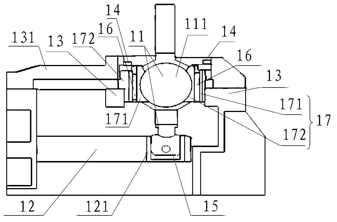
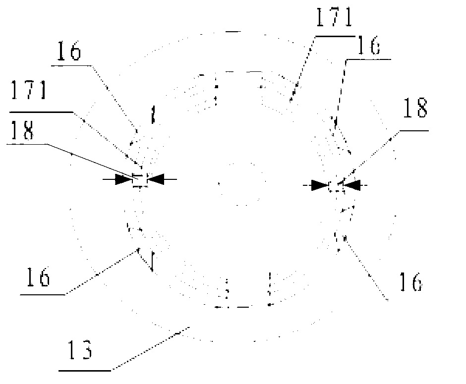
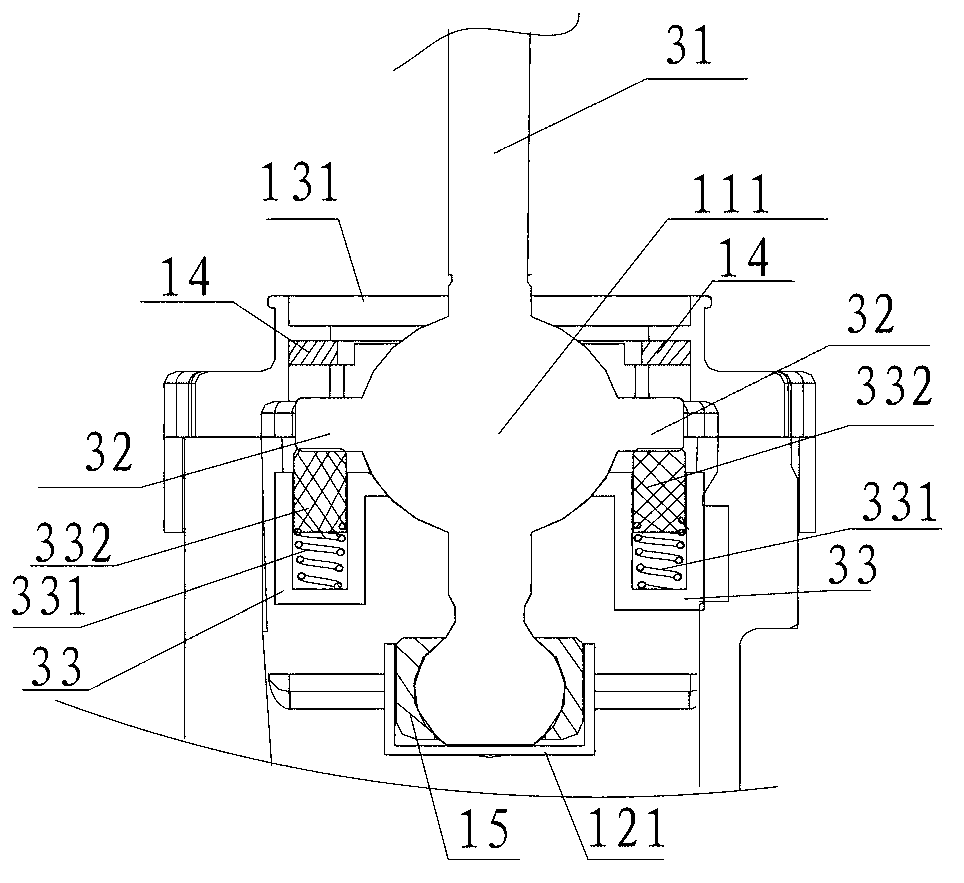
[0022] Embodiments of the present invention provide a transmission operating mechanism, such as figure 1 As shown, it includes a ball head piece 11 and a shift selector shaft 12, one end of the ball head piece 11 is clamped in a slot 121 of the shift selector shaft 12, and the ball head piece 11 and the shift selector shaft 12 are both located in the casing of the transmission A damping pad 14 is provided between the gap between the ball head piece 11 and the upper end cover 131 of the housing, and a damping spacer 15 is provided in the slot 121 of the shift selector shaft.

[0023] In the transmission operating mechanism provided by the embodiment of the present invention, since the damping spacer 15 is provided in the slot 121 of the shift selector shaft 12, when th...


PUM


Abstract

The invention provides a transmission control mechanism, and relates to parts of motor vehicles. The transmission control mechanism solves the problem that when an existing transmission control mechanism is used, and an engine is in an idling condition and an urgent acceleration condition, an existing transmission can generate abnormal sounds. The transmission control mechanism comprises a bulb piece and a selecting shifting gear shaft, wherein one end of the bulb piece is arranged inside a clamping groove of the selecting shifting gear shaft in a clamped mode, the bulb piece and the selecting shifting gear shaft are respectively arranged inside a shell body of a transmission, vibration reducing pads are arranged in gaps between the bulb piece and an upper end cover of the shell body, and a vibration reducing isolating sleeve is arranged inside the clamping groove of the selecting shifting gear shaft.

Description

technical field [0001] The present invention relates to motor vehicle components, and more particularly to transmission operating mechanisms. Background technique [0002] The automobile transmission is a set of transmission devices used to coordinate the engine speed and the actual driving speed of the wheels, so as to exert the best performance of the engine. The transmission can generate different speed ratios between the engine and the wheels during the driving of the car, and the gear change can be realized by the control mechanism of the transmission, so that the engine can work in its best dynamic performance state. [0003] Usually, the transmission control mechanism mainly includes a control lever, a ball joint and a shift selector shaft, wherein one end of the ball joint is connected with the control lever, and the other end of the ball joint is clamped in the slot of the selector shift shaft. , the ball head piece and the shift selection shaft are all located in ...

Claims


Application Information

Patent Timeline
IPC IPC(8): F16H59/02F16F15/04F16F15/08
Inventor 黄勇刘文超李景富贾楠王雪亮王增利延志刚刘浩王李王开元
Owner GREAT WALL MOTOR CO LTD
Learn More