Spring cable
A spring cable, spring wire technology, applied in the direction of fiber mechanical structure, etc., can solve the problems of anti-side pressure, anti-bending flexibility to be improved, anti-side pressure, bending flexibility is not ideal, affecting the performance of optical cables, etc., to achieve production. The method is simple and easy to learn, has a wide range of applications, and has the effect of low cost
- Summary
- Abstract
- Description
- Claims
- Application Information
AI Technical Summary
Problems solved by technology
Method used
Image

Examples
Embodiment 1
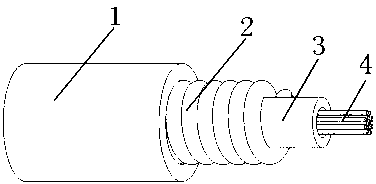
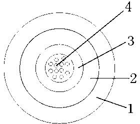
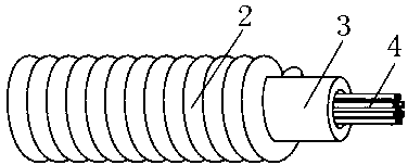
[0034] Please see Fig. 1 to Fig. 5, a kind of spring cable, comprises the central beam tube 3 that is located in the center and the inside is hollow, a plurality of optical fibers 4 located in the inner hollow part of the central beam tube; it is characterized in that there is a spring outside the central beam tube The armor layer 2, and the spring armor layer is close to the outer wall of the central beam tube, and the spring wires of the adjacent layers in the spring armor layer are close to each other; the spring armor layer is extruded with a sheath layer 1.
[0035] The above-mentioned spring cable is characterized in that the central bundle tube is made of polybutylene terephthalate or polypropylene.
[0036] The above-mentioned spring cable is characterized in that the optical fiber is a single-mode fiber or a multi-mode fiber.
[0037] Furthermore, the spring cable mentioned above is characterized in that the optical fiber is G652 type or G655 type or G657 type...
Embodiment 2
[0044] Please see Fig. 6 and Fig. 8, and in combination with Fig. 1 to Fig. 5, a device for forming a spring armor layer on a spring cable is characterized in that it includes a bundle tube coil with a central bundle tube 3 wound around it 51. A steel wire tray 52 with a spring wire 21 and a mold 53 formed by a spring armor layer; The shaft 523 is rotatably fixed on the second fixed frame 521; the first fixed frame is fixed on the foundation, the second fixed frame is fixed on the foundation, and the first fixed frame and the second fixed frame are parallel; Behind the pipe coil and in a fixed state, the axis of the steel wire coil is higher than the upper edge of the bundled tube coil; the mold formed by the spring armor layer is located in front of the bundled tube coil. In this device, the central bundle tube is released from the bundle tube tray and passes through the center hole of the mold formed by the spring armor layer, and is pulled forward; at the same time, the s...
Embodiment 3
[0047] Please see Fig. 7 and Fig. 9, and in combination with Fig. 1 to Fig. 5, a device for forming a spring armor layer on a spring cable is characterized in that it includes a bundle tube coil with a central bundle tube 3 wound around it 51. The steel wire coil 52 with the spring wire 21 wound around it, and the mold 53 formed by the spring armor layer; the beam tube coil is rotatably fixed on the first fixed frame 511 through the shaft, and the steel wire coil is fixed on the winch cage 522 And can rotate around the fixed axis to release the spring wire; the first fixed frame is fixed on the foundation, and the winch cage can rotate around the axis 31 of the central bundle tube; the mold formed by the spring armor layer is located in front of the bundle tube pan. In this device, the central bundle tube is released from the bundle tube tray and passes through the center hole of the mold formed by the spring armor layer, and is pulled forward; at the same time, the spring wi...
PUM
 Abstract
Description
Claims
Application Information
 - R&D
- Intellectual Property
- Life Sciences
- Materials
- Tech Scout
- Unparalleled Data Quality
- Higher Quality Content
- 60% Fewer Hallucinations
Browse by: Latest US Patents, China's latest patents, Technical Efficacy Thesaurus, Application Domain, Technology Topic, Popular Technical Reports.
© 2025 PatSnap. All rights reserved.Legal|Privacy policy|Modern Slavery Act Transparency Statement|Sitemap|About US| Contact US: help@patsnap.com