Proximity sensor, RFID card reader and proximity sensing method
A proximity sensor and card reader technology, applied in the field of proximity sensor, RFID card reader and proximity sensing, can solve the problems of frequent battery replacement, sensitive power consumption, user inconvenience, etc., to achieve ultra-low power consumption and prolong service life , the effect of reducing workload
- Summary
- Abstract
- Description
- Claims
- Application Information
AI Technical Summary
Problems solved by technology
Method used
Image

Examples
Embodiment 1
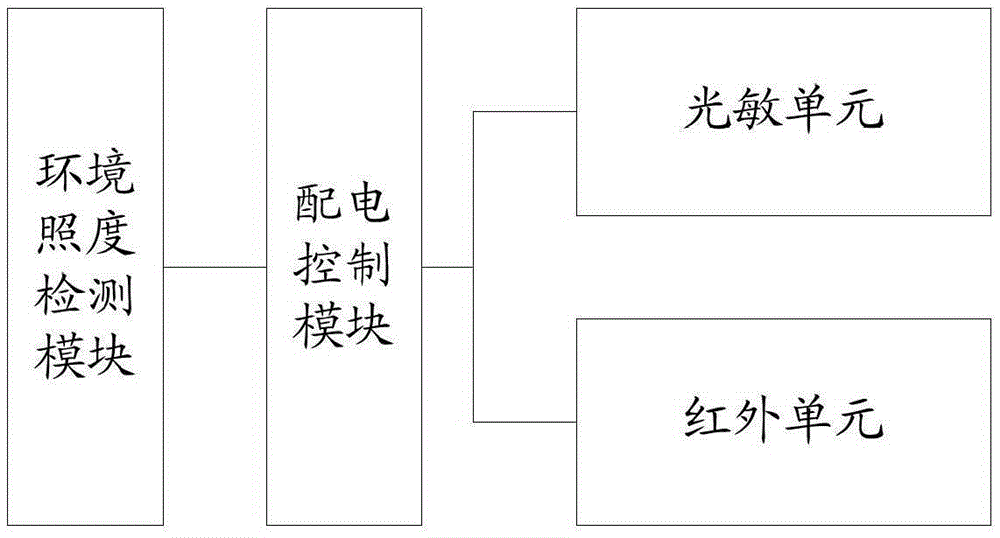
[0025] Proximity sensors of the present invention, such as figure 1 shown, including:
[0026] The ambient illumination detection module is used to detect whether the ambient illumination is higher than a threshold;
[0027] The power distribution control module is used to control the photosensitive unit to be powered on and the infrared unit to be powered off when the ambient illuminance is higher than the threshold, and to control the infrared unit to be powered on and the photosensitive unit to be powered off when the ambient illuminance is lower than or equal to the threshold ;
[0028] The photosensitive unit is used to detect the light change, and generate a pulse signal when the light change reaches a predetermined value;
[0029] The infrared unit is used for periodically emitting infrared rays and receiving infrared rays, and generating pulse signals when receiving infrared rays.
[0030] As mentioned above, the proximity sensor has two working modes, one is photos...
Embodiment 2
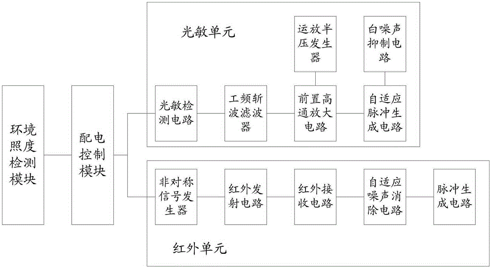
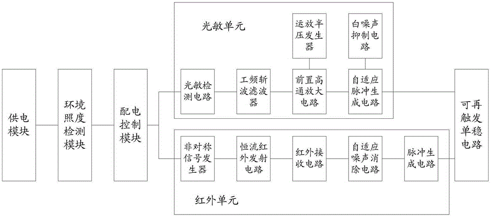
[0033] In this example, if figure 2 As shown, the photosensitive unit includes a photosensitive detection circuit connected in sequence, a power frequency chopper filter, a pre-high-pass amplifier circuit and an adaptive pulse generation circuit, and an operational amplifier half-voltage generator and a white noise suppression circuit. The half voltage generator is connected with the pre-high-pass amplifier circuit, and the white noise suppression circuit is connected with the adaptive pulse detection circuit.
[0034] The resistance value of the photoresistor in the photosensitive detection circuit changes as the light changes, thereby causing a voltage change, and the subsequent circuit can identify the card swiping action according to the voltage change. Since the photoresistor is sensitive to visible light, and most lighting lamps use a 50Hz power frequency power supply, the photoresistor will generate a 50Hz electrical interference signal. The power frequency chopper fi...
Embodiment 3
[0040] In this example, if figure 2 As shown, the infrared unit includes an asymmetric signal generator, an infrared transmitting circuit, an infrared receiving circuit, an adaptive white noise elimination circuit and a pulse generating circuit connected in sequence.
[0041] The asymmetrical signal generator is used to generate the infrared signal, which is composed of CMOSICM555. In order to save energy, the gap transmission method of transmitting infrared signals every 50ms is adopted. The high level is 0.1ms, the low level is 50ms, and the duty ratio is 500:1, which can greatly reduce power consumption. At the same time, since it takes 300-400ms for ordinary people to swipe their cards, the transmission interval of 50ms is also to make the user experience good without feeling delayed.
[0042]The operating voltage of the infrared emission circuit is 3-4.5 volts, and the operating voltage of the infrared emission tube is 1.2-1.6 volts. In order to keep the infrared emissi...
PUM
 Abstract
Description
Claims
Application Information
 - R&D Engineer
- R&D Manager
- IP Professional
- Industry Leading Data Capabilities
- Powerful AI technology
- Patent DNA Extraction
Browse by: Latest US Patents, China's latest patents, Technical Efficacy Thesaurus, Application Domain, Technology Topic.
© 2024 PatSnap. All rights reserved.Legal|Privacy policy|Modern Slavery Act Transparency Statement|Sitemap